Heat Exchanger Integration in F1 Cars
Explains how F1 teams optimize radiator placement, ducting, and 3D-printed cores to balance cooling needs with aerodynamic drag and performance.
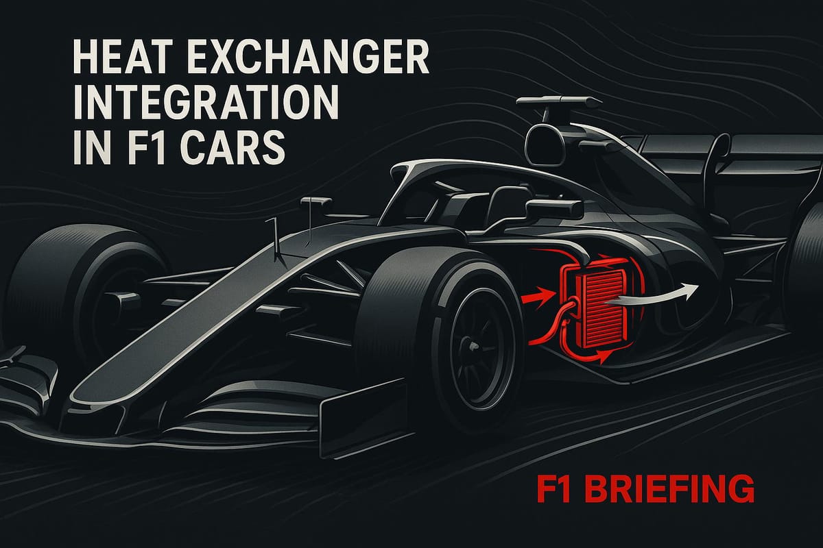
Heat exchangers in Formula 1 cars are critical for managing engine and system temperatures under extreme racing conditions. These components ensure optimal performance by transferring heat from fluids to the surrounding air. Teams use advanced designs like liquid-to-air intercoolers to cool compressed air from turbochargers operating at pressures over 4.7 bar absolute (54 psi above atmospheric pressure). However, balancing cooling efficiency with aerodynamic performance is a constant challenge.
Key points:
- Larger radiators improve cooling but increase drag, reducing aerodynamic efficiency.
- Advanced tools like CFD simulations and 3D printing enable precise designs for improved heat transfer and reduced size.
- Teams adjust cooling setups for specific tracks using modular bodywork options like louvers and larger outlets.
- Materials like 3D-printed metal allow for compact, efficient heat exchangers that optimize airflow and cooling.
The article explores how F1 teams fine-tune heat exchanger placement, airflow management, and design strategies to balance cooling needs with aerodynamic goals. These innovations not only enhance race performance but also influence high-performance road car designs.
Research and Engineering Advances in F1 Heat Exchanger Design
Thermal Management Studies in F1
F1 teams rely heavily on advanced computer modeling to predict how their cars will handle heat during races. These models strike a delicate balance between efficient cooling and aerodynamic performance. By combining 1D thermo-fluid models with 3D CFD simulations, engineers can analyze airflow and coolant behavior under various race conditions. This data is then fed into lap-simulation tools, allowing teams to recreate an entire race scenario, factoring in engine power changes, vehicle speeds, and weather conditions like ambient temperature and altitude.
This virtual calibration process lets teams fine-tune their cooling systems before they even reach the track. For instance, they can simulate extreme scenarios, such as a sweltering race day with temperatures soaring above 95°F or a high-altitude circuit where thinner air challenges cooling efficiency. These simulations monitor water, oil, and ERS cooling loops, predicting radiator core and coolant outlet temperatures while also identifying risks like boiling or cavitation. Engineers then use this data to design modular cooling setups that can be adjusted for specific circuits - think larger rear exits or higher-density cores tailored to weather and track demands. These tools have not only improved system performance but also driven advancements in design and production methods.
New Materials and Manufacturing Methods
The rise of additive manufacturing, or 3D printing, has revolutionized how F1 heat exchangers are designed. Traditional brazed-plate or tube-and-fin methods limit the complexity of internal structures. In contrast, 3D printing allows for intricate internal fin patterns, variable channel shapes, and lattice structures. These designs increase the heat-transfer surface area while maintaining a compact size and improving flow distribution.
Companies like Conflux Technology, which has roots in F1, now produce 3D-printed metal heat exchangers for both motorsport and high-performance road vehicles. These components can be customized with specific fin densities and geometries on both the air and coolant sides, enabling engineers to optimize the balance between heat transfer and pressure drop. For example, Conflux developed a 3D-printed liquid-to-air charge-air cooler for the Donkervoort P24 RS, cutting the inlet tract length by two-thirds while still meeting cooling requirements.
Another major development comes from Reaction Engines. Their rocket-engine precooler technology, originally designed to handle air temperatures of up to 1,832°F in hypersonic flight, has been adapted for F1. Mercedes has used this technology to create highly efficient charge-air coolers. These compact cores deliver exceptional thermal performance, managing the intense heat from turbochargers operating at intake manifold pressures above 4.7 bar absolute, all while saving space and minimizing drag.
Measuring Cooling Drag and Performance Impact
In F1, "cooling drag" refers to the aerodynamic penalty caused by channeling air through sidepod inlets, ducts, and radiator cores instead of maintaining a sealed, streamlined configuration. Teams measure this drag penalty using a combination of wind tunnel tests and CFD simulations. These tools evaluate both the external airflow around the car and the internal flow through the cooling system.
Engineers test aerodynamic performance at speeds between 150–190 mph, experimenting with different inlet sizes, duct designs, and radiator resistances. They assess how these changes affect the drag coefficient and downstream aerodynamic components like the rear wing and diffuser. This data is then incorporated into lap-time simulations, which calculate how different cooling setups impact overall performance. For instance, larger radiators may increase drag on straights but improve engine reliability or power output, creating a trade-off that teams can quantify.
To minimize cooling drag without sacrificing thermal performance, teams focus on creating more efficient cores using advanced fin designs or 3D-printed geometries. These innovations allow for the same heat rejection with a smaller frontal area. Internal airflow management is another key focus, with engineers carefully shaping inlets, ducts, and outlets to ensure air flows smoothly through the system and exits in a way that supports downstream aerodynamics. Some designs even channel air toward the rear wing, recovering energy that would otherwise contribute to drag. On race weekends, teams use modular cooling setups with adjustable bodywork panels or gills, allowing them to adapt to changing temperatures by either tightening bodywork for low drag or opening up for extra cooling capacity as needed.
Design and Integration: How F1 Teams Package Heat Exchangers
Placement Options and Layout Strategies
When it comes to the cooling and aerodynamics puzzle, F1 teams get creative with how they position heat exchangers. It's like solving a complex 3D jigsaw puzzle. Typically, the main water and oil radiators find their place in the sidepods, while additional radiators and intercoolers are tucked around or above the power unit under the engine cover. Smaller components, like coolers for the ERS, electronics, and battery, are often nestled near the central chassis or close to the fuel cell, with their own dedicated ducting systems. In the compact world of V6 turbo-hybrid engines, five radiators - covering water, oil, two ERS circuits, and the charge-air cooler - are tightly packed into the sidepod and engine cover areas.
The 2024 season has shown just how much variation exists in these strategies. Ferrari’s SF-24, for instance, uses a central radiator fed by air from the airbox, paired with radiators positioned under the engine cover. Meanwhile, the Mercedes W15 took a more traditional route, raising its water and oil radiators. This decision slightly compromised the car’s center of gravity but allowed for cleaner undercuts and lower-drag sidepods compared to its earlier radical designs. Across the grid, teams like Red Bull, Ferrari, Mercedes, and McLaren all employ unique heat exchanger layouts, proving there’s no one-size-fits-all solution. Each team tailors its layout to maximize aerodynamic efficiency, with some opting for taller, narrower radiators and others choosing lower, broader designs, depending on their aerodynamic goals.
A growing trend is the use of liquid-to-air intercoolers instead of the traditional air-to-air systems. This approach allows the intake-charge cooler to be positioned away from the external airstream - often in front of or above the engine - while a secondary water radiator in the sidepod handles heat dissipation. Both Ferrari and Mercedes have embraced this setup, placing water-to-air intercoolers away from direct airflow. This design improves aerodynamic flexibility, even though it adds complexity with an extra coolant circuit and secondary radiator. The trade-off is worth it for many teams, as the streamlined sidepod shapes offer significant aerodynamic advantages.
Airflow Management and Aerodynamic Testing
Efficient airflow through heat exchangers is all about precise internal duct design. To maximize heat transfer, teams design ducts as diffusers. Air enters through a narrow inlet, expands as it passes over the radiator core, and then reconverges to accelerate the flow and minimize drag. The radiator core itself sits in the low-speed section of the duct, giving the air time to transfer heat. Larger outlet cross-sections ensure smooth airflow and prevent choking or backpressure issues.
Teams rely on CFD simulations to refine duct shapes, core angles, and outlet geometries. These designs are then tested in the wind tunnel to validate their performance. Engineers focus on metrics like pressure drop across the radiator core, airflow rates through cooling circuits, the drag impact of inlet and outlet sizes, and how hot-air plumes affect rear downforce and balance. Track telemetry and temperature data are used to create detailed cooling maps, which help teams determine the optimal inlet and outlet sizes for specific race conditions.
Interestingly, outlet designs can vary from left to right to account for uneven radiator loads in the sidepods. The placement and orientation of these outlets - whether side, top, or rear-blown - are carefully tuned to limit drag, avoid disrupting airflow in critical areas, and sometimes even enhance flow structures over the beam wing or rear suspension. This level of precision helps teams keep cooling systems as aerodynamically efficient as possible, especially on high-speed circuits like Circuit of The Americas.
Track-Specific Cooling Adjustments
F1 teams further fine-tune their cooling systems to adapt to the unique demands of each circuit. They prepare multiple bodywork options, including different sidepod inlet shapes, cooling "gills" or louvers on the engine cover, and alternative rear outlet panels. These modular designs allow teams to adjust for varying ambient temperatures and race conditions. For hot races, such as those in the U.S. summer where temperatures can exceed 86°F (30°C), teams open larger outlets, add louvers, or use higher-drag engine covers to ensure adequate cooling, even if it means sacrificing a bit of straight-line speed.
In cooler conditions, the focus shifts to minimizing drag by using the tightest bodywork possible, with smaller inlets and outlets. This not only reduces drag but also helps warm up the tires more effectively. Under the constraints of the cost cap, teams can't afford an endless array of bespoke cooling setups. Instead, they prioritize a small number of modular solutions - like reusable panels and inlets - that can be adapted for circuits with similar cooling needs. This approach helps control costs while still accommodating the extremes of high-altitude tracks like Mexico City and cooler venues. Bodywork gills and louvers are particularly versatile, as they can be adjusted to balance cooling and drag for each race. However, larger openings do come with trade-offs, such as increased drag and potential disruptions to airflow over the rear wing and beam wing.
How To Cool An F1 Car | F1 TV Tech Talk | Crypto.com

Performance Metrics and Design Trade-Offs
F1 Heat Exchanger Technologies: Traditional vs Advanced Manufacturing Comparison
Cooling Efficiency vs. Aerodynamic Drag
When it comes to Formula 1 car design, striking the right balance between cooling efficiency and aerodynamic drag is a constant challenge. Cooling is directly tied to lap-time performance, so engineers rely on key metrics like heat rejection (measured in kilowatts), temperature margins relative to component limits, pressure drops across the heat exchanger core, and the aerodynamic drag penalty (noted as ΔCd). Larger inlets and ducts can improve cooling by directing more air through radiators, but they also increase drag and disrupt airflow over crucial aerodynamic surfaces, such as the rear and beam wings. To find the sweet spot, teams use a mix of CFD simulations, wind tunnel testing, and on-track telemetry to fine-tune inlet sizes and core thicknesses, all while operating within tight thermal constraints.
The 2024 Formula 1 grid showcases how different teams approach this trade-off. For example, Red Bull's RB20 integrates the intercooler within the sidepod, lowering the car's center of gravity and enabling tighter bodywork. On the other hand, Ferrari's SF-24 places the intercooler ahead of the power unit, favoring a more conservative design that enhances reliability. Meanwhile, Mercedes' W15 has returned to a conventional radiator layout with elevated water and oil radiators after its more radical approaches with the W13 and W14 faced challenges. These design choices highlight how teams juggle thermal management and aerodynamic efficiency to maximize performance.
Thermal Limits and Reliability Concerns
Every component of an F1 power unit - whether it's the internal combustion engine, turbocharger, MGU-H, MGU-K, ERS battery, or gearbox - operates within strict thermal limits. If cooling systems fall short, teams may need to dial back engine performance by using richer fuel mixtures, reducing turbo speeds, or limiting ERS deployment. All of these adjustments come at the cost of lap time. The drive to minimize drag often pushes these thermal limits, forcing teams to recalibrate their performance strategies.
Some teams opt for more conservative cooling setups to prioritize reliability, even if it means accepting a slight drag penalty. Others push the boundaries, aiming to reduce drag as much as possible, even at the risk of detuning the engine or experiencing component failures. These trade-offs become especially critical during race weekends. For instance, insufficient cooling during long stints or safety-car periods - when airflow drops and temperatures rise - can lead to power unit failures. Teams must carefully weigh the risks of reliability issues against the potential gains in performance.
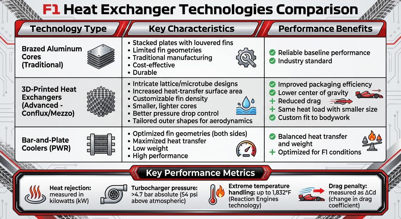
Comparing Heat Exchanger Technologies
In the world of F1 cooling systems, brazed aluminum cores remain a staple. These cores, built with stacked plates and louvered fins, are known for their durability and cost-effectiveness. However, their fin geometries are somewhat limited by traditional manufacturing techniques. Enter 3D-printed heat exchangers, developed by companies like Conflux and Mezzo, which leverage intricate lattice or microtube designs to increase the heat-transfer surface area without increasing the overall size. This allows for smaller, lighter cores that improve packaging and lower the car's center of gravity.
These advanced designs also offer better control over pressure drop. By customizing fin density and local flow passages, engineers can either reduce pressure losses for a given heat load or extract more performance without adding extra drag. Additionally, the outer shape of these exchangers can be tailored to fit tightly within the car's bodywork, improving aerodynamic efficiency. Bar-and-plate coolers from PWR feature optimized fin geometries on both the ambient and fluid sides, maximizing heat transfer while keeping weight low. Meanwhile, Mezzo's microtube heat exchangers are promoted as lightweight and compact, capable of withstanding the high-pressure, high-temperature conditions typical in F1. These innovations highlight the ongoing push in F1 to refine cooling systems for better performance and tighter packaging.
Conclusion: What F1 Heat Exchanger Integration Teaches Us
Core Design Principles for Optimal Integration
In Formula 1, integrating heat exchangers isn’t just about managing engine temperatures - it’s a balancing act that blends cooling, aerodynamics, and power unit packaging into a single, cohesive system. Every design choice, from core thickness to duct angles, is carefully evaluated for its impact on cooling performance, aerodynamic drag, and overall car balance.
By tailoring radiator geometry to follow the car’s internal airflow and body contours, teams can achieve efficient heat rejection with minimal size and pressure drop. This not only allows for smaller inlets and smoother external surfaces but also enhances airflow to key aerodynamic components like the rear wing and diffuser. Simplifying ducting and shortening flow paths further improve cooling efficiency by reducing weight and pressure losses.
Teams also adapt their cooling systems to track-specific conditions using modular inlets, louvered panels, and alternative radiator configurations. Pre-race simulations, incorporating local weather data such as ambient temperatures (in Fahrenheit) and track altitude, help determine the ideal bodywork setup to maintain thermal limits while minimizing lap-time losses.
These strategies highlight how F1 teams optimize every detail to stay competitive. And as technology advances, the sport is already looking ahead to the next generation of cooling solutions.
Future Developments in F1 Cooling Systems
The future of F1 cooling will continue to push the boundaries of design and technology. Additive manufacturing and advanced materials are set to play a major role, offering groundbreaking possibilities. Companies like Conflux Technology are already leading the way with 3D-printed charge-air coolers, which feature customized fin densities and micro-structured internal passages. These innovations deliver superior heat transfer in smaller, lighter packages.
Looking ahead to 2026, the elimination of the MGU-H and upgrades to the MGU-K will demand new thermal management strategies. These changes in power unit architecture will alter heat rejection requirements, likely driving teams toward even more integrated and efficient cooling systems. At the same time, budget cap constraints will force teams to carefully weigh the benefits of cutting-edge heat exchangers against their costs and potential reliability risks.
In this ever-evolving landscape, F1 teams will need to remain as resourceful and strategic as ever to maintain their competitive edge.
FAQs
How do F1 teams ensure effective cooling without compromising aerodynamics?
F1 teams masterfully juggle the need for cooling and aerodynamic efficiency by seamlessly incorporating heat exchangers into their car designs. These components are strategically placed within the sleek bodywork to maximize airflow, keeping the engine and critical systems cool while reducing drag and preserving downforce.
The use of advanced materials and state-of-the-art engineering techniques further enhances this process. Teams craft compact, efficient cooling systems that not only save weight but also minimize any negative impact on aerodynamics. This meticulous design and technological ingenuity ensure F1 cars deliver top-tier performance, even in the most demanding conditions.
How is 3D printing used in the development of F1 heat exchangers?
3D printing has become a game-changer in the development of F1 heat exchangers. One of its standout advantages is speeding up prototyping, allowing engineers to test and tweak designs much faster than traditional methods. This means they can refine and perfect components in record time.
Another major benefit is the ability to produce intricate geometries that enhance cooling performance without compromising the car's aerodynamic profile. These complex shapes, often impossible to achieve with conventional manufacturing, directly contribute to better thermal management on the track.
On top of that, 3D printing enables the creation of lightweight parts - a critical factor in maximizing a car’s overall performance. By reducing weight while maintaining strength, F1 teams can achieve faster speeds and improved handling. This cutting-edge manufacturing process keeps teams at the forefront of innovation, ready to meet the ever-changing technical challenges of the sport.
How do F1 teams adjust cooling systems for different tracks?
F1 teams meticulously adjust their cooling systems to meet the specific challenges of each track. This involves tweaking heat exchanger configurations, fine-tuning coolant flow rates, and reshaping air ducts to maintain optimal temperature control. These modifications are influenced by variables like ambient temperature, humidity, and the track's design.
Additionally, teams rely on electronic controls to strike a balance between cooling efficiency and aerodynamics. On high-speed circuits, minimizing drag becomes a top priority, whereas tighter, slower tracks often demand more aggressive cooling solutions to compensate for reduced airflow. This delicate balancing act ensures the cars stay reliable without compromising speed or performance.