New F1 Rules: How Power Units Meet Fuel Targets
How 2026 F1 fuel and ERS limits force teams to balance combustion, turbo, battery deployment, cooling and lap-by-lap fuel plans.
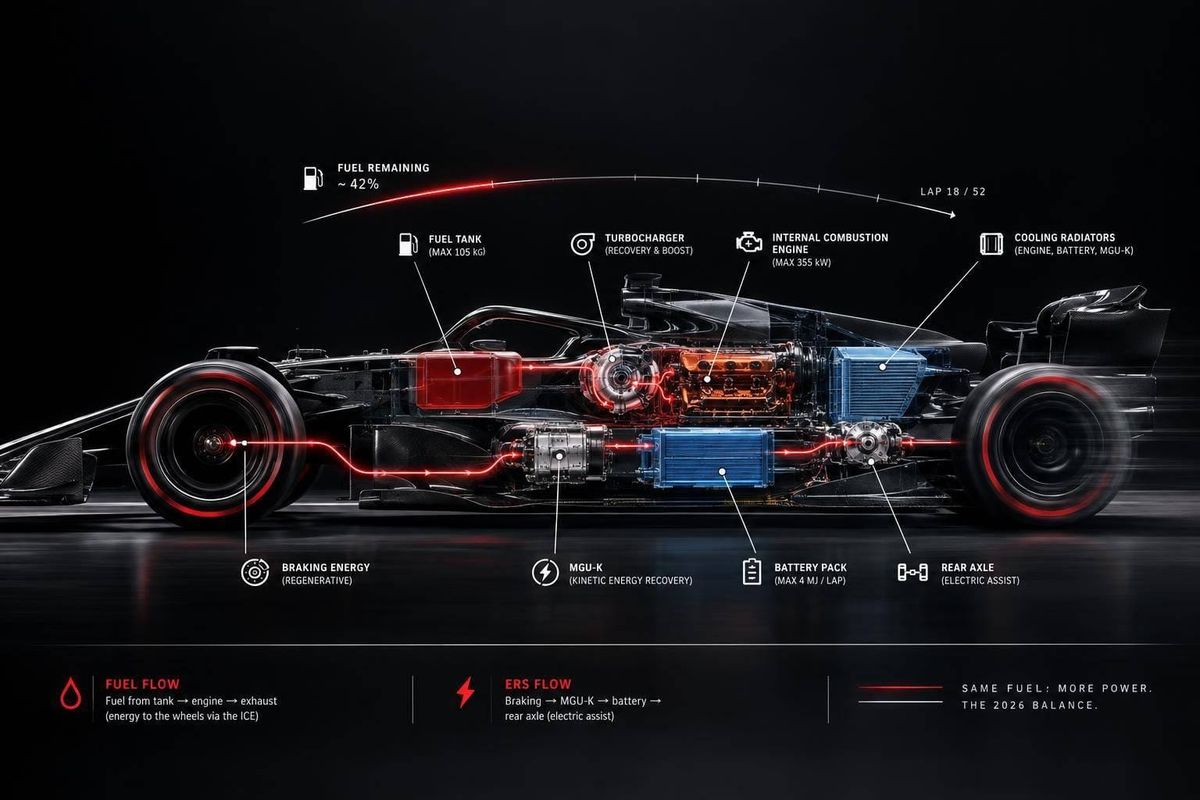
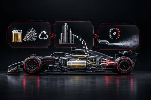
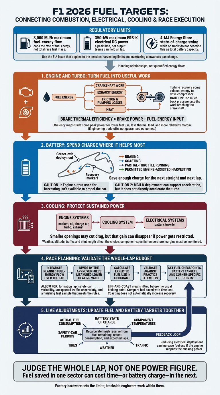
Meeting F1’s 2026 fuel targets takes more than using less fuel. I’d start by checking fuel use and battery charge together: the 3,000 MJ/h fuel-energy-flow cap limits delivery rate, while 350 kW of electrical power is a peak - not an output teams can hold all lap.
Here’s how I’d connect the pieces:
- Engine and turbo: Get more work from the fuel without excess heat or turbo stress.
- Battery: Spend charge where it helps acceleration most, then plan enough recovery for the next lap.
- Cooling: Balance lower drag against the temperatures needed to keep power available.
- Race planning: Use practice data to set fuel checkpoints and lift-and-coast points that save fuel with little time loss.
- Live adjustments: Update fuel and battery targets as traffic, weather, tires, and safety-car periods change.
My takeaway: <u>judge the whole lap, not one power figure</u>. Fuel saved in one sector can cost time - or battery charge - in the next.
F1 2026: From Energy Limits to Race Pace
2026 F1 Engine & Battery Deployement Explained (MGU-K)
sbb-itb-7c68254
Improve Combustion and Turbo Efficiency
Fuel energy takes four paths: crankshaft work, exhaust energy, friction and pumping losses, or heat. The turbine recovers some exhaust energy to drive the compressor. But there’s a limit: too much back pressure cuts the work reaching the crankshaft.
Turn Fuel Energy Into Engine Work
Fuel chemistry affects evaporation, flame speed, and knock resistance. How much energy reaches the crankshaft depends on injector targeting, air motion, ignition timing, compression ratio, chamber shape, and friction losses.
On the dyno, engineers measure torque, fuel-energy input, exhaust temperature, and coolant and oil temperatures. They then calculate brake thermal efficiency = brake power ÷ fuel-energy input. Transient tests check whether the engine map still works during corner-exit acceleration.
Peak-power maps aim for maximum output. Efficiency maps give up some peak power for lower fuel use, less thermal load, and more reliability margin.
These are engineering trade-offs, not guaranteed outcomes. Results depend on rpm, load, fuel properties, and hardware; permitted operating-mode changes remain subject to the rules.
Once combustion is mapped, engineers can seek further gains by matching boost delivery to the circuit.
Match Turbo Settings to Track Conditions
Engineers match compressor airflow and pressure ratio to efficient operating regions, avoiding surge at low flow and choke at high flow. The turbine must extract enough work without creating excessive back pressure, which forces the pistons to work harder to expel exhaust.
Wastegate control and combustion calibration shape response. MGU-K deployment can support acceleration, but it does not directly accelerate the turbo.
| Factory hardware choice | Response | Peak-efficiency potential | Cooling demand | Reliability concern |
|---|---|---|---|---|
| Smaller, lower-inertia assembly | Usually faster | May struggle at high airflow | High speed and temperature can become limiting | Overspeed and bearing stress |
| Larger compressor and turbine | Usually slower | Can favor sustained high airflow | Depends on matching and operating point | Structural loads and transient behavior |
| Lower-restriction turbine | May weaken low-flow response | Can reduce high-load pumping losses | Changes where exhaust heat is carried | Must still provide sufficient compressor drive |
Factory hardware sets the range; weekend calibration sets the target. Engineers adjust permitted boost targets, wastegate control, ignition calibration, and cooling configuration - not compressor or turbine geometry.
At altitude or in hot air, maintaining oxygen delivery can require a higher compressor pressure ratio. That increases turbo speed and discharge temperature. Track telemetry should therefore check actual fuel use alongside boost response, exhaust temperature, and turbo speed. Meeting a fuel target means little if the calibration overheats or puts reliability at risk.
Those efficiency gains also reduce how much battery energy the team must spend later in the lap.
Plan Battery Use and Cooling
Allocate Battery Energy Across the Lap
Battery deployment helps only if the car still meets its fuel target. The lap plan must balance stored energy, recovery, and cooling. FIA technical material specifies a 350-kW maximum ERS-K electrical DC power and a 4-MJ Energy Store state-of-charge swing while on track. Use the FIA issue that applies to the session: harvesting limits and overtaking allowances can change.
The MGU-K can recover energy during braking, coasting, partial-throttle running, and permitted engine-assisted harvesting, which uses engine work to recharge the battery. Track harvested energy, losses, state of charge, and deployment at the same points each lap.
Focus deployment on corner exits and zones where the driver needs to defend, while saving enough charge for the next straight. Don’t spend charge where traction limits acceleration. Engine output used for harvesting isn’t available to propel the car. Model normal, recharge, and attack laps to check that recovery restores charge without too much time loss or heat. Using less electrical power shifts more work back to the engine.
| Deployment approach | Performance | Overtaking reserve | Recharge demand | Thermal load |
|---|---|---|---|---|
| Aggressive | Maximum legal assistance at the exits and straights where it helps most; strongest short-term lap-time or attack benefit | Small unless the plan sets charge aside | High; needs strong braking, coasting, or engine-assisted harvesting and may require harvesting laps later | High in the MGU-K, inverter, battery, cabling, and rear-end cooling system |
| Balanced | Assistance focused on high-value exits, with controlled deployment elsewhere | Moderate reserve for defense or a planned pass | Medium; aims to restore charge within the normal lap rhythm | Medium and generally easier to repeat across a stint |
| Conservative | Lower or shorter deployment saves charge and reduces peak electrical demand | Largest reserve for a late pass, defense, or recovery from traffic | Lower immediate demand, though later laps may need deliberate recharge | Lowest short-term thermal load and greatest margin in hot or higher-altitude conditions |
That electrical budget depends on cooling that keeps temperatures steady throughout the stint.
Choose Cooling to Avoid Power Loss
Coordinate coolant, oil, charge-air, battery, inverter, turbo, and exhaust cooling. Both harvesting and deployment add heat. Factory radiator sizing, duct routing, and seals set the cooling capacity. The race team then chooses permitted cooling bodywork to suit the weather, altitude, traffic, and stint length.
| Cooling configuration | Drag | Thermal margin | Sustained deployment |
|---|---|---|---|
| Low-drag | Lowest, helping top speed and reducing fuel demand | Narrowest, especially in hot weather, traffic, or at altitude | Can be strong at first but difficult to sustain over a stint |
| Balanced | Moderate | Enough for the expected circuit and weather range | Usually the most reliable compromise for race distance |
| High-cooling | Highest, with possible top-speed and fuel penalties | Greatest protection for coolant, oil, charge air, battery, inverter, turbo, and exhaust systems | Best able to sustain deployment in hot, high-load, higher-altitude, or traffic-heavy conditions |
Check the choice in practice. Hot weather reduces heat rejection, altitude reduces cooling-air mass, and traffic disrupts airflow. Compare fuel flow, speed profile, and sustained deployment alongside lap time. Smaller openings may cut drag, but that gain can disappear if power gets restricted.
Use component-specific temperatures rather than one global limit. Sensor location, airflow, altitude, and calibration all change the margin, so a single limit is too blunt.
With the cooling map and battery targets set, engineers can build the race-weekend fuel plan, placing lift points and recharge laps where they cost the least time.
Put the Race-Weekend Fuel Plan Into Practice
Once combustion, turbo, battery, and cooling limits are set, the team turns them into a lap-by-lap fuel budget.
Build and Test the Circuit Energy Budget
Convert the lap’s fuel-energy limit into fuel mass using the fuel’s lower heating value. The FIA’s 3,000 MJ/h maximum fuel-energy flow caps the rate of fuel energy - not total race fuel mass. Integrate the planned flow over the lap, then divide by the approved fuel’s measured lower heating value to calculate expected fuel use in kilograms.
Allow for the formation lap, safety-car variability, unexpected traffic, uncertainty, and a finishing fuel sample that meets the rules. Then set fuel-remaining checkpoints. This budget helps identify where the driver can lift with the least time loss.
Use factory simulation, dyno validation, and practice telemetry to turn the circuit model into race and qualifying targets. Factory hardware sets the limits; trackside engineers work within them. Check predictions against practice laps with matched tires and traffic, accounting for wind and changes in track conditions. Set battery targets alongside fuel checkpoints, and give the driver corner-specific lift and braking points.
Choose Lift Points That Limit Time Loss
Lift-and-coast means lifting before the usual braking point. Test each candidate lift point by comparing fuel saved with time lost - not by choosing the longest coast. Speed, braking-zone length, tire condition, and traffic all affect the outcome.
A long approach to a slow corner may save fuel with little time loss. An approach where the driver needs to defend may be a poor choice. Lifting and harvesting can work together, but coasting does not automatically increase recovery.
| Approach | Fuel savings | Battery recovery | Lap-time cost | Positioning risk |
|---|---|---|---|---|
| Early lift-and-coast | Direct fuel saving | None to moderate, depending on braking and ERS settings | Low to moderate on suitable approaches | More exposed to attack; too much coasting can disrupt braking references |
| Conventional braking | Little additional saving | Normal braking recovery | Baseline | Best for defending or attacking |
| More harvesting | Not necessarily a fuel saving | Higher recovery when braking and regulations allow | More compromise in deployment and braking feel | Reduced deployment or altered braking can leave the car vulnerable |
Adjust Fuel Targets as Conditions Change
Once the race starts, update the plan using actual fuel consumption rather than pre-race estimates. Recalculate the finish reserve from fuel remaining, recent consumption, and expected laps.
Safety-car running usually cuts fuel demand, but it also changes battery recovery and deployment opportunities. Traffic can add acceleration and heat. Wet conditions change grip, wheelspin, visibility, and tire preparation. If the reserve drops below target, shift fuel-saving instructions to lower-risk corners. Reducing electrical deployment can increase fuel use if the engine supplies the missing power.
Use public timing to track gaps and lap-time loss, and team telemetry to monitor fuel remaining and battery state of charge. Check regulatory limits against the applicable FIA documents. As the reserve and conditions change, revise permitted maps, lift instructions, and temperature-margin targets - not factory hardware.
Conclusion: Link Efficiency With Race Execution
Once the fuel budget is set, track execution determines whether the plan works. Rules set the limits. Race pace depends on how combustion, turbo response, battery deployment, cooling, and lift points work together.
Teams must turn those limits into lap-by-lap deployment and cooling decisions. The electrical-power limit defines peak output - not power a team can maintain throughout a lap - and doesn’t guarantee a fast stint. Simulation and telemetry show the lap-time trade-offs between deployment timing, cooling drag, and energy harvesting costs.
Use this final checklist to connect factory efficiency with track execution:
- Validate the budget: Check the full energy budget against practice data and FIA limits.
- Protect margins: Check minimum state of charge and temperature margins for the engine, turbo, battery, inverter, and cooling system at critical sectors.
- Choose low-cost lifts: Compare fuel saved with time lost. Confirm any energy recovery benefit rather than assuming it.
- Adjust targets together: Update fuel and electrical targets as traffic, weather, tires, and safety-car periods change.
- Separate facts from estimates: Keep FIA rules, measured results, and engineering estimates clearly labeled.
FAQs
Can recharging the battery increase fuel use?
Yes - recharging the battery can indirectly increase fuel use. Charging and discharging lose energy compared with transferring it more directly. More combustion is needed to make up for those losses.
The goal, though, is to reduce total fuel use by recovering energy from braking or exhaust and using it later - all within strict FIA fuel-flow and ERS deployment limits.
How do teams choose between fuel savings and lap time?
Teams use simulations and real-time telemetry to weigh speed now against fuel needs over the full race. In qualifying, they run minimal fuel loads to prioritize speed, since track position often matters more than fuel conservation.
During races, teams manage the 2026 fuel limit of 70 kg (about 154 lb) using lift-and-coast and preset attack, defense, or fuel-save modes. These settings balance fuel use and energy deployment based on the circuit, tire wear, and what drivers will need late in the race.
When does extra cooling outweigh its drag penalty?
Extra cooling is worth the added drag when power-unit heat loads threaten performance or risk thermal runaway. That’s especially true with the 2026 battery’s high-energy cycles and the 350 kW MGU-K. Cooling adds weight and drag, but it protects battery cells and prevents oil degradation during long races.
Teams weigh that protection against low-drag setups for straights. They often use active aerodynamics to offset the energy cost of maintaining top speeds.