Why Turbocharger Materials Matter in F1
How material choices determine F1 turbo heat tolerance, spool-up, efficiency and service life under new rules.
In F1, turbo materials decide how much heat the unit can take, how fast it responds, and whether it lasts long enough to avoid penalties. With exhaust heat near 1,830°F (1,000°C), shaft speeds up to 125,000 rpm, and only 3 turbo units usually allowed per driver for the season, the wrong material costs both power and reliability.
Here’s the short version:
- Hot-side parts need to resist creep, oxidation, and thermal fatigue
- Cold-side parts need low weight to cut rotating inertia
- Shafts and bearings must handle heat soak, vibration, and very high speed
- Mar-M246 can hold shape better than some Inconel options at high rpm
- For 2026, the loss of the MGU-H puts more focus on low inertia and turbo response
If I strip it down even more, the article makes one main point: material choice is not a detail. It affects boost, energy recovery, clearances, spool-up, and service life across roughly 5,000 to 7,000 km of use.
| Area | What matters most | Main effect |
|---|---|---|
| Turbine wheel | Heat strength and creep resistance | Holds shape and keeps efficiency |
| Turbine housing | Thermal fatigue resistance | Keeps clearances under control |
| Compressor wheel | Low mass and fatigue strength | Helps spool-up |
| Shaft and bearings | Strength, low friction, heat resistance | Supports speed and response |
| Wastegate | Erosion and thermal shock resistance | Keeps boost control steady |
So if you want the plain answer, it’s this: better turbo materials let teams run harder, longer, and with less risk.
Power Unit 101 with PETRONAS: Turbocharger, EXPLAINED!

sbb-itb-7c68254
The stresses that drive material selection
Turbocharger materials have to match the job of each part. The turbine, compressor, shaft, and bearings don't live in the same world. Each one deals with its own mix of heat, rpm, and vibration.
Heat, creep, oxidation, and thermal fatigue
The turbine wheel has the toughest life on the turbo. It sits in the path of hot exhaust gas, and that heat drives creep - slow, permanent deformation under constant heat and load. During a race, the part also goes through repeated heating and cooling. Those cycles build thermal fatigue, which can lead to cracks over time.
Oxidation is a different issue, but it hits the same hot-side parts. At extreme temperatures, exhaust gases attack the surface of turbine components and wear the material down. A turbine wheel with good oxidation resistance keeps its shape longer. That helps hold tight clearances and maintain high efficiency. That's why hot-side components need a mix of high-temperature strength, creep resistance, and oxidation resistance. And once thermal damage starts, the part becomes more vulnerable before centrifugal load and vibration finish the job.
Centrifugal load, vibration, and shaft speed
At very high rpm, centrifugal force is brutal. It tries to tear the wheel apart. At 95,000 rpm, the loads on a turbine wheel are huge. At that speed, even slight deformation can tighten clearances and increase the risk of rub.
The compressor side deals with the same basic spinning forces, but it sees less thermal stress than the turbine. The shaft and bearings sit between turbine-side heat and compressor-side conditions, so they have to handle high-speed rotation and vibration while also resisting heat soak from the turbine housing. In that kind of setup, dimensional stability matters just as much as raw strength.
Weight, packaging, and FIA constraints

Heat and load aren't the only problems. Engineers also have to fit everything into a very tight package. When space is limited, there's less room for thicker sections or extra shielding. So the material has to stay light without giving up strength.
Lower-density materials can cut rotating inertia and help throttle response. But there's a catch: they still need to survive the punishment of a race weekend.
Those trade-offs shape whether a turbo is fast enough, light enough, and tough enough to make it through the weekend. They also explain why the turbine, compressor, shaft, bearings, and wastegate each end up with different material choices.
Materials used in each turbocharger component
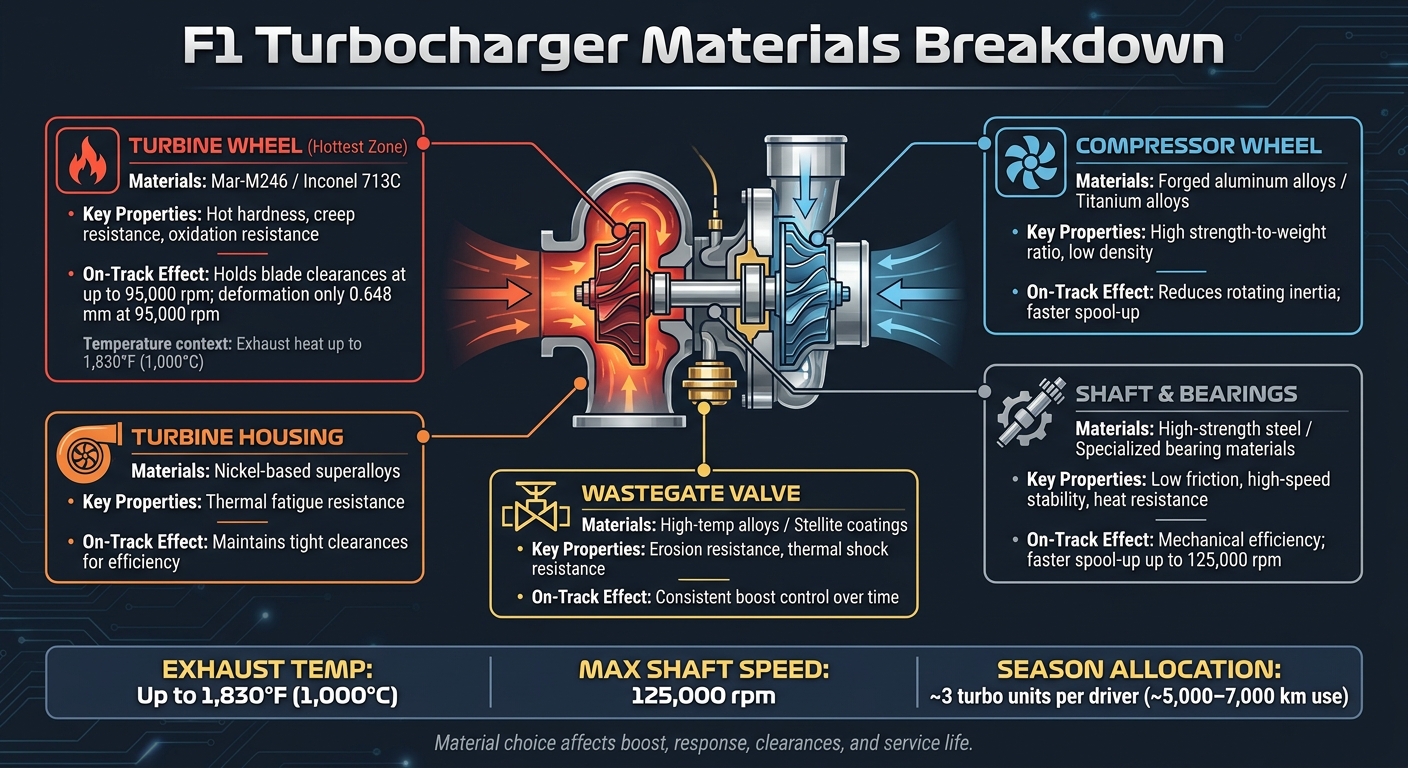
F1 Turbocharger Materials: Components, Properties & On-Track Effects
Each turbo part needs its own material. The hot side deals with brutal heat. The cold side cares more about weight and speed. Then you have the shaft and bearings stuck in the middle, dealing with both. So the turbine, compressor, shaft, bearings, and wastegate all call for different material choices.
Turbine wheel and turbine housing
The turbine wheel takes the worst abuse in the whole turbo. It has to fight creep, oxidation, and shape change while handling both heat and centrifugal force. That’s why nickel-based superalloys are the go-to choice.
Inconel 713C is a common starting point. When a design needs more hot hardness and creep resistance, engineers often step up to Mar-M246. Mar-M246 contains 10% cobalt and 10% tungsten, which helps the wheel keep blade clearances under extreme conditions and hold efficiency. The downside is lower ductility than Inconel 713C. So the decision usually comes down to this: do you want stronger resistance to deformation, or a material that gives a bit more before it fails?
The turbine housing stays in the same nickel-superalloy family. Its wall thickness is set to balance thermal fatigue resistance with the need to keep clearances tight.
Compressor wheel, housing, shaft, and bearings
Compressor wheels are usually made from forged aluminum alloys. The reason is simple: they’re light and have high fatigue strength. Lower rotating mass also helps the turbo spool up faster.
Titanium alloys can also be used when engineers want even less rotating mass. On paper, that sounds like a small change. On track, it can matter.
The shaft has a rough job. It carries torsion, heat soak, and vibration at very high speed, so high-strength steel is the standard pick. Bearings are mostly about low friction and shaft stability, both of which affect spool-up and mechanical efficiency.
These material picks shape three big things:
- Heat tolerance
- Rotating mass
- Service life
Wastegate and supporting hardware
The wastegate opens and closes over and over in high-velocity exhaust flow. That means the valve and seat need to resist erosion and thermal shock if boost control is going to stay accurate over time. Wastegate parts use high-temperature alloys, and Stellite coatings protect the seat from erosion.
| Component | Typical Material | Required Property | Main On-Track Effect |
|---|---|---|---|
| Turbine Wheel | Mar-M246 | Hot hardness & creep resistance | Holds blade clearances at high rpm |
| Turbine Wheel | Inconel 713C | High-temperature strength | Standard durability; higher ductility |
| Turbine Housing | Nickel-based superalloys | Thermal fatigue resistance | Maintains tight clearances for efficiency |
| Compressor Wheel | Forged aluminum / Titanium alloys | High strength-to-weight ratio | Reduces rotating inertia; faster spool-up |
| Shaft & Bearings | High-strength steel / specialized bearing materials | Low friction; high-speed stability | Mechanical efficiency; faster spool-up |
| Wastegate Valve | High-temp alloys / Stellite coatings | Erosion & thermal shock resistance | Consistent boost control over time |
Those trade-offs lead straight to the next issue: how material properties show up as power, response, and durability.
How material properties shape power, efficiency, and durability
Turbo materials set the ceiling for heat, shaft speed, and service life. In F1, that means material behavior affects lap time directly, not just whether the part survives.
Higher temperature tolerance and energy recovery
If hot-side materials can take higher exhaust temperatures without deforming, the turbine can pull more energy from the exhaust stream. That extra energy can turn into higher boost pressure and more energy for the MGU-H to recover.
There’s also a geometry piece here. When deformation stays low, engineers can keep blade-tip clearances tighter even at very high rpm. Once that shape starts to drift, efficiency takes a hit. Boost pressure falls, and the MGU-H has less energy available.
Lower rotating mass and turbo response
A lighter rotating assembly spins up with less delay. Cut mass from the compressor wheel or other rotating parts, and the turbo reacts faster when the driver gets back on the throttle.
That shows up most on corner exit. The driver wants boost NOW, not a moment later. Less mass helps the turbo build speed sooner, which sharpens response.
A turbine wheel that holds its shape better at speed helps too. It keeps blade-tip clearances more consistent, which lets engineers run tighter tolerances and reduce energy leakage between the blade tips and the housing.
Durability across race weekends and season allocations
Under FIA allocation limits, a turbo has to last for thousands of kilometers without giving away performance. The main threats are creep and thermal warping.
If the turbine wheel starts rubbing the housing, failure can happen fast. In the worst cases, that can lead to turbocharger failure right away and even catastrophic engine damage.
| Material Property | Technical Benefit | On-Track Effect |
|---|---|---|
| High-temp strength | Handles higher exhaust temperatures without deforming | More turbine work and better MGU-H energy recovery |
| Creep resistance | Prevents blade stretch and deformation over time | Maintains aerodynamic efficiency and helps avoid DNFs |
| Oxidation resistance | Resists material loss in the exhaust stream | Preserves performance across multiple race allocations |
| Low density | Reduces rotational inertia | Faster spool-up and sharper throttle response |
| Fatigue life | Resists cracking from thermal cycling and vibration | Reliability over high-mileage race weekends |
| Thermal conductivity | Manages heat distribution and thermal gradients | Reduces warpage and maintains tight blade-tip clearances |
Lower mass helps response. But stronger superalloys often deal with heat and load better over a full season. That trade-off is pushing teams toward tougher alloys, smarter coatings, and lighter bearing systems.
Where F1 turbo materials are heading
Advanced alloys, coatings, and bearing technologies
Heat and durability limits are now pushing teams toward tougher alloys, better coatings, and lighter rotating parts.
One clear move is toward Mar-M246 turbine wheels. Their higher hot hardness and creep resistance help the wheel keep its shape under extreme heat and rpm. In simulations, the wheel deforms by just 0.648 mm at 95,000 rpm. That smaller change cuts rub risk and helps preserve efficiency.
Coatings are changing too. Ceramic coatings on housing surfaces help reduce heat transfer into the bearing housing. That lowers oil-coking risk and helps protect nearby parts. At the same time, anti-wear coatings on shafts and bearings cut friction and mechanical loss at high rpm, which helps durability.
Teams are also leaning on coupled thermo-structural simulation tools to spot thermal stress-induced warpage before physical prototyping. That gives engineers a cleaner way to place material only where stress demands it, trimming weight without giving up strength.
| Emerging Trend | Engineering Challenge Addressed | Expected Effect on Turbo Design |
|---|---|---|
| Mar-M246 superalloy | Creep and deformation at high rpm and temperature | Thinner, lighter turbine blades that maintain aerodynamic shape under load |
| High-cobalt/tungsten compositions | Oxidation and hot hardness at extreme exhaust temperatures | Ability to run higher exhaust gas temperatures for greater energy recovery |
| Ceramic coatings | Heat transfer into the bearing housing | Lower oil-coking risk and better protection for nearby components |
| Anti-wear shaft and bearing coatings | Friction and mechanical loss at high rpm | Lower energy losses and longer service life |
| Coupled FEA simulation | Thermal stress-induced warpage | Optimized, non-uniform geometries that reduce weight without compromising strength |
How future regulations could shift material priorities
That shift matters even more under the 2026 FIA power unit rules. The MGU-H is being removed, which means the turbocharger will no longer have an electric motor helping control shaft speed or recover energy straight from the shaft.
Without MGU-H support, lower inertia and faster transient response matter more. Put simply, the turbo has to react faster on its own. That puts more pressure on material choices to deliver both low weight and long life.
The 2026 rules also require 100% sustainable fuels. Those fuels bring different combustion characteristics, which adds another layer to the material problem. Teams will need materials that can balance durability, response, and efficiency at the same time.
Conclusion: What turbocharger materials decide in F1
In F1, turbo materials now play a big role in how much heat a team can handle, how fast the turbo responds, and how long it stays legal and competitive.
FAQs
Why not use one material for the whole turbo?
Because each turbocharger part deals with a different kind of punishment.
The turbine wheel sits in extreme heat and stress, so it needs a material that can take that abuse without failing. Bearing housings and seals, on the other hand, work in lower-temperature areas where durability and insulation matter more.
By using different materials, engineers can tune each part for performance, reliability, and long service life instead of asking one material to do every job badly.
Why does lower turbo inertia matter more in 2026?
Lower turbo inertia matters even more in 2026 because it cuts turbo lag and helps the turbo spool faster. In an F1 engine, that can make a big difference.
Why? Because faster spool-up helps the engine hold optimal boost pressure more consistently. And when boost comes in sooner, throttle response feels sharper too. In a high-performance F1 power unit, those small gains can have a big effect on how the car reacts when the driver gets back on the power.
What usually fails first in an F1 turbo?
Usually, the turbocharger’s turbine or nearby hardware fails first. That’s not surprising when you consider the conditions: extreme heat and very high rotational speeds put those parts under constant stress.
That said, the MGU-H has its own weak spots. Bearings and seals, in particular, can become failure points when conditions get harsh. This is especially true for parts made from advanced polymers such as PEEK and PTFE, which are often pushed hard in these systems.