Compressed Air Systems for F1 Pit Lanes
Size and test compressed air/nitrogen pit-lane systems for repeatable F1 stops: storage, hoses, regulators, under-load pressure, and safety.
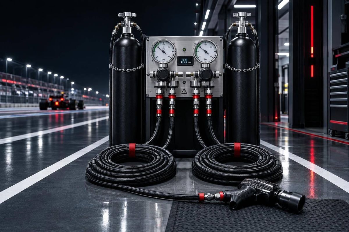
I’d judge an F1 gas supply by pressure at the wheel guns under load - not by the cylinder gauge. Test all four guns together, plus any jack releases sharing the supply, and check that tool-inlet pressure stays within the required range - typically 290–363 psi (20–25 bar).
My checklist covers the whole gas path:
- Supply: Choose air or nitrogen, control moisture, and size usable reserves for repeated stops.
- Delivery: Match regulators, hoses, and couplings to peak demand; keep crew and jack paths clear.
- Testing: Measure pressure during overlapping gun use, backup changeovers, and back-to-back stops. Pressure alone does not prove correct wheel fastening.
- Safety and rules: Secure cylinders, isolate and bleed lines before service, assess nitrogen ventilation, and check the FIA rules in force.
<u>The goal is steady tool pressure, safe handling, and enough reserve for the next stop.</u>
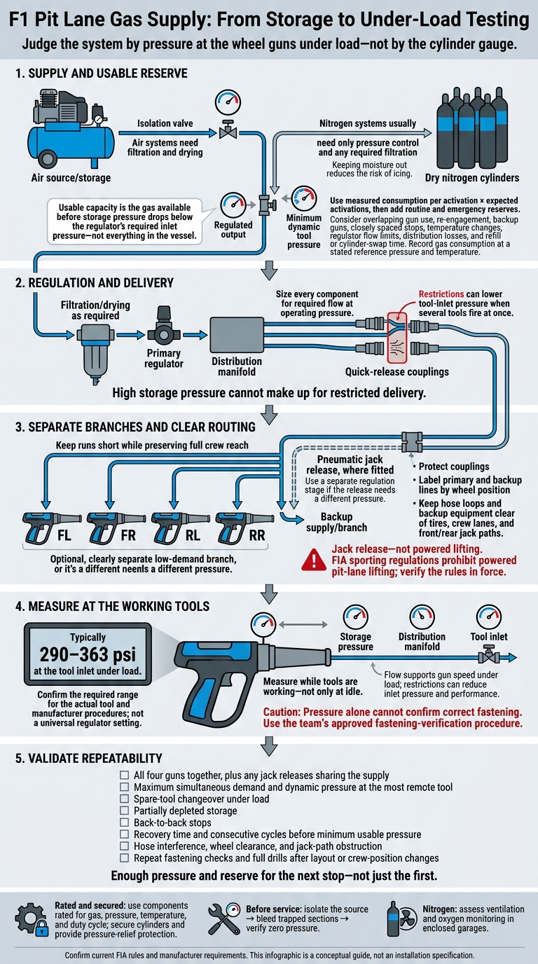
F1 Pit Lane Gas Supply: From Storage to Under-Load Testing
How Gas Reaches Pit Lane Tools
Gas Storage, Regulators, and Supply Lines
Air systems need filtration and drying. Nitrogen systems usually need only pressure control and any required filtration. Keeping moisture out reduces the risk of icing. Regulators and enough flow help maintain steady pressure and restore it after repeated hits.
Line size and couplings then determine how much pressure reaches the tool under load.
[Air source/storage]       [Dry nitrogen cylinders]
         │                          │
 [Isolation valve]          [Isolation valve]
         └────────────┬─────────────┘
         [Filtration/drying as required]
                      │
             [Primary regulator]
                      │
          [Distribution manifold]
                      │
             [High-flow hoses]
                      │
         [Quick-release couplings]
                      │
       [Wheel guns / pneumatic tools]
Pressure sets torque; flow keeps the gun fast under load. Restrictions in the lines can lower inlet pressure when several tools fire at once. Pressure can also drop across regulators under load, so size each component for the required flow at operating pressure.
Wheel-Gun Speed, Torque, and Fastening Checks
Restricted gas delivery lowers inlet pressure, slows the gun, and weakens the hit. Measure pressure near the gun while it works under load. If performance drops, check the hose’s inside diameter, its length, and restrictions at the couplings. High storage pressure cannot make up for restricted delivery.
The next section uses pressure under load, not the idle gauge reading, to size the system.
Jacks and Other Pit Lane Tools
F1 front jacks are usually manual, though some have a pneumatic release. Include that gas demand only when the jack has one: it can affect wheel-gun pressure during the same stop. If the release needs a different pressure than the wheel guns, use a separate regulation stage.
Put wheel guns on a high-flow branch and jacks on a separate low-demand branch. Keeping the branches separate helps maintain steady wheel-gun pressure when other tools cycle during the stop.
sbb-itb-7c68254
Sizing the Gas Supply and Planning the Pit Box
Storage Capacity and Pressure Under Load
Once you know the delivery path, size the supply for peak stop demand. Use measured gas consumption per activation, accounting for wheel-gun cycles, overlapping use, jacks, and other pneumatic devices. Before comparing consumption with storage capacity, record it at a stated reference pressure and temperature - for example, in standard liters per minute or standard cubic feet per minute.
Usable capacity is the gas available before storage pressure drops below the regulator’s required inlet pressure - not everything in the vessel. Treat storage pressure, regulated output, and minimum dynamic tool pressure as separate values. Allow for temperature changes, regulator flow limits, and distribution losses.
Multiply consumption per activation by the expected number of activations. Then add routine and emergency reserves for re-engagement, backup guns, and closely spaced stops. Specify how long refilling or swapping cylinders takes, and plan access that doesn’t cross crew paths.
Hose Routing and Distribution Options
With the supply sized, route the lines to maintain pressure at the tool. Choose hose internal diameter based on peak demand and allowable pressure drop. Keep runs short, protect couplings, and label primary and backup lines by wheel position.
Leave enough slack for the crew’s full reach, but keep loops clear of tires and jack paths. Assign each gun a pickup and stow point. Check bend radius, abrasion, and crushing risks with the wheel crew.
           FRONT JACK PATH  -  keep clear
                      Car nose
       FL wheel                       FR wheel
   [Gun + parked spare]          [Gun + parked spare]
          | FL lines                 | FR lines
          +------------+-------------+
                       |
            [Protected manifold]
            [Primary / backup branches]
                       |
          +------------+-------------+
          | RL lines                 | RR lines
   [Gun + parked spare]          [Gun + parked spare]
       RL wheel                       RR wheel

            REAR JACK PATH  -  keep clear

Protected storage area, outside crew movement corridors:
[Primary storage] → [Isolation / regulator] → Distribution
[Backup supply]   → [Isolation / regulator] → Backup branches

Jack paths show crew movement, not powered lifting.
These options can overlap. No single layout fits every pit box.
| Distribution option | Pressure stability | Hose length | Redundancy | Serviceability | Layout complexity |
|---|---|---|---|---|---|
| Central manifold | Can balance delivery paths when sized correctly; test simultaneous demand | May need longer runs to outer wheel positions | One manifold can become a shared failure point without a bypass | Central access makes inspection easier | Moderate; needs careful routing across the box |
| Side-mounted distribution | Can shorten lines on one side and separate front/rear demand | Often shorter for nearby positions | Can isolate one side, but may need duplicate regulators and manifolds | Easy to access when mounted outside crew lanes | Moderate to high, depending on isolation and backup provisions |
| Dedicated wheel-position lines | Stable delivery when each line is correctly sized and isolated | May need more total hose and fittings | Strong fault isolation; one failed line need not disable all corners | More components to inspect and identify | High; needs consistent labeling and parking |
Tool Timing and Pit Stop Testing
Test the system under stop conditions, not just at static pressure. Check gas delivery during gun activation, wheel exchange, fastening checks, and jack lowering. Pressure alone does not prove correct fastening. Keep enough reserve for a second engagement or a backup gun after the nominal cycle. Include jack release, not powered lifting: FIA sporting regulations prohibit powered pit-lane lifting.
Record gun retrieval and backup deployment times, hose interference, wheel clearance, and jack-path obstruction. Log activation duration, gas use, and dynamic pressure at storage, the manifold, and the tool inlet.
Repeat testing with overlapping activations, partially depleted storage, and back-to-back stops. Measure recovery time and the number of consecutive cycles possible before reaching minimum usable pressure. Check both gas delivery and crew movement against the team’s acceptance limits.
F1 Wheel Guns EXPLAINED!
System Reliability, Safety, and Trade-Offs
Once the layout is set, reliability depends on tracking down pressure loss, securing stored gas, and meeting the rules.
Pre-Stop Checks and Troubleshooting
If delivery drops under load, trace the fault to the source, regulator, line, or tool. Before each session, check storage pressure, regulator output, leaks, coupling lockup, and hose damage. Load-test both the primary and spare guns. Test any pneumatic jack-release mechanism separately, including its reset, so faults are easier to isolate.
Use these readings to find where pit-stop performance breaks down.
| Symptom | Possible causes | Measurement points | Corrective actions |
|---|---|---|---|
| Slow wheel-gun speed | Restricted coupling, low supply, leak, or damaged gun | Tank, regulator outlet, and gun inlet under load | Repair leaks, remove restrictions, or substitute a tested gun |
| Inconsistent torque delivery | Worn socket, damaged fastener, misalignment, or unstable delivery | Gun inlet during fastening; socket condition; team fastening check | Replace worn parts, correct alignment, and verify fastening independently |
| Slow jack release, where fitted | Sticking valve, blocked exhaust, seal leak, or control fault | Actuator inlet, valve, exhaust, and release time | Service the mechanism and verify safe support and reset |
| Slow supply recovery | Insufficient reserve, limited refill output, or hidden leak | Storage pressure, recovery time, and leak-down rate | Repair leaks or improve reserve/refill capability |
| Far-corner pressure loss | Crushed hose, restrictive fittings, or manifold imbalance | Manifold and remote tool inlet under equivalent load | Correct the affected line and retest all wheel positions |
Change one component at a time. If the fault follows the gun, suspect the tool. If it stays at the wheel position, check the supply path. Use synchronized video to separate retrieval, activation, fastening, and release delays.
Pressure alone cannot confirm correct fastening. Use the team’s approved torque, transducer, visual, or audit procedure.
After checking performance faults, treat trapped energy and nitrogen handling as safety issues - not routine maintenance details.
Pressure-System Safety
Use components rated for the gas, pressure, temperature, and duty cycle. Secure cylinders in the pit box, protect valves and hoses, keep crew lanes clear, and provide pressure-relief protection. Stored gas can rupture equipment, launch projectiles, and cause hose whip.
Before servicing, isolate the source, bleed trapped sections, and verify zero pressure. Nitrogen can displace oxygen in enclosed garages, so assess ventilation and oxygen monitoring. Follow manufacturer procedures rather than generic regulator settings.
OSHA’s compressed-gas requirements cover cylinder inspection and relief devices. Follow applicable venue, safety, fire, and pressure-equipment rules.
With hazards controlled, aim for the smallest acceptable pressure loss - not the highest possible pressure.
Balancing Pressure, Capacity, and Backup Equipment
Balance response time, reach, and redundancy against weight and clutter. Set an operating margin that maintains pressure under peak load. Increasing pressure must not replace fixing restrictions. Give backups assigned storage and connection points outside crew paths.
| Choice | Benefit | Trade-off or control |
|---|---|---|
| Higher pressure | May improve tool response | Stay within component ratings and monitor wear |
| Larger reserves | Extend usable supply | Add weight, space, and securing requirements |
| Shorter hoses | Reduce delivery losses | Preserve full crew reach |
| Backup equipment | Allows fast substitution | Prevent clutter and incorrect connections |
Acceptance checklist
- [ ] Test maximum simultaneous demand and dynamic pressure at the most remote tool.
- [ ] Remove restrictions and protect lines.
- [ ] Test spare-tool changeover under load.
- [ ] Repeat fastening checks and full pit-stop drills after layout or crew-position changes.
Then verify that the tested setup matches the rules in force.
Checking Current Rules and Technical Sources
As of October 15, 2026, check the current FIA technical and sporting regulations, including amendments in force. The supplied 2026 technical text states that wheel-fastener tools in qualifying, sprint, and race sessions may use compressed air, nitrogen, or electricity. Confirm the exact edition, issue number, effective date, and wording.
Check McLaren’s original publication date and wording before citing its historical account of gas restrictions. Put official rules, team material, and manufacturer manuals first. Label numerical specifications with their source, or identify them as illustrative assumptions. Record the verification date.
Conclusion: Reliable Supply for Repeatable Pit Stops
Once the supply is sized and the lines are routed, check performance under load. A wheel gun can do its job only if enough gas reaches its inlet. Gas reserve, pressure, flow, routing, and backups must support the crew’s timing while the system is under load.
Test the complete setup under race-like conditions: all four guns, any pneumatic jack releases, and a rapid second stop. Supply must recover fast enough to keep the second stop consistent with the first. If recovery falls short, the setup fails - even when the tools meet spec.
Published specs cover the tool, not the full system. Team settings, internal modifications, and control logic remain hidden. What counts is repeatable pressure and recovery along the entire gas path - from storage through regulation and hoses to the tool inlet.
FAQs
Why choose nitrogen over compressed air?
Teams use nitrogen because it’s an inert, dry gas. It keeps moisture from condensing inside wheel guns and pneumatic lines, helping prevent corrosion and keeping tools running reliably during sub-2-second pit stops.
Nitrogen also helps limit pressure swings during extreme pit lane temperature changes. That steady pressure delivers consistent power to remove and secure wheel nuts fast.
How do teams detect leaks during a race?
Teams spot possible leaks by tracking real-time sensor data through the pit wall’s telemetry feeds and checking it against pit-stop performance data. GPS and timing add context, while immediate feedback flags unusual behavior that could point to pressure loss.
After the stop, teams review high-speed video frame by frame alongside recorded telemetry. This helps them confirm where the issue occurred and sharpen the diagnosis for future stops.
What happens if a wheel gun loses pressure mid-stop?
If a wheel gun loses pressure during a pit stop, it may not have enough power to remove or tighten the wheel nut. That can leave the nut stuck or the tire improperly secured. The result: a major delay, a worse race result, or safety risks - including an unsafe release. Teams reduce these risks with regular maintenance, backup systems, and rigorous simulation training.