F1 Composites: Impact Resistance in Carbon Fibre
How layup, fiber angles, resin toughness and geometry control impact damage and energy absorption in F1 carbon parts.
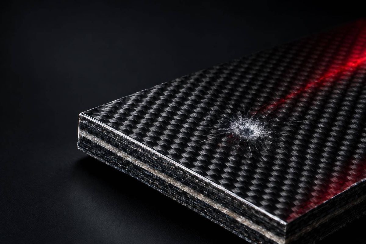
More carbon fiber does not automatically mean better impact protection. I start with the load case: wheel contact needs strong load paths and joints, debris strikes need penetration resistance, and barrier impacts need controlled crushing.
Here’s how I break down the design choices:
- Fiber direction and layup: 0°, 90°, and ±45° plies handle different loads. Unidirectional, woven, and hybrid stacks each trade strength, impact behavior, and weight.
- Joints and attachments: Local reinforcement and gradual thickness changes help spread loads without creating weak transitions.
- Resin and processing: Toughened resin can slow cracks, but poor bonding, voids, or the wrong cure can erase those gains.
- Geometry and weight: Crash structures must absorb energy through progressive crushing, while the survival cell protects the driver’s space.
- Testing and inspection: I would not judge a struck part by its appearance. <u>Hidden damage can reduce its remaining strength.</u>
The goal is to match the fibers, resin, joints, and shape to the impact - not simply add more material.
How Formula 1 Cars Are Crash Tested
sbb-itb-7c68254
Wheel Contact, Debris Strikes, and Barrier Impacts
F1 Carbon Fibre: Three Impact Types Compared
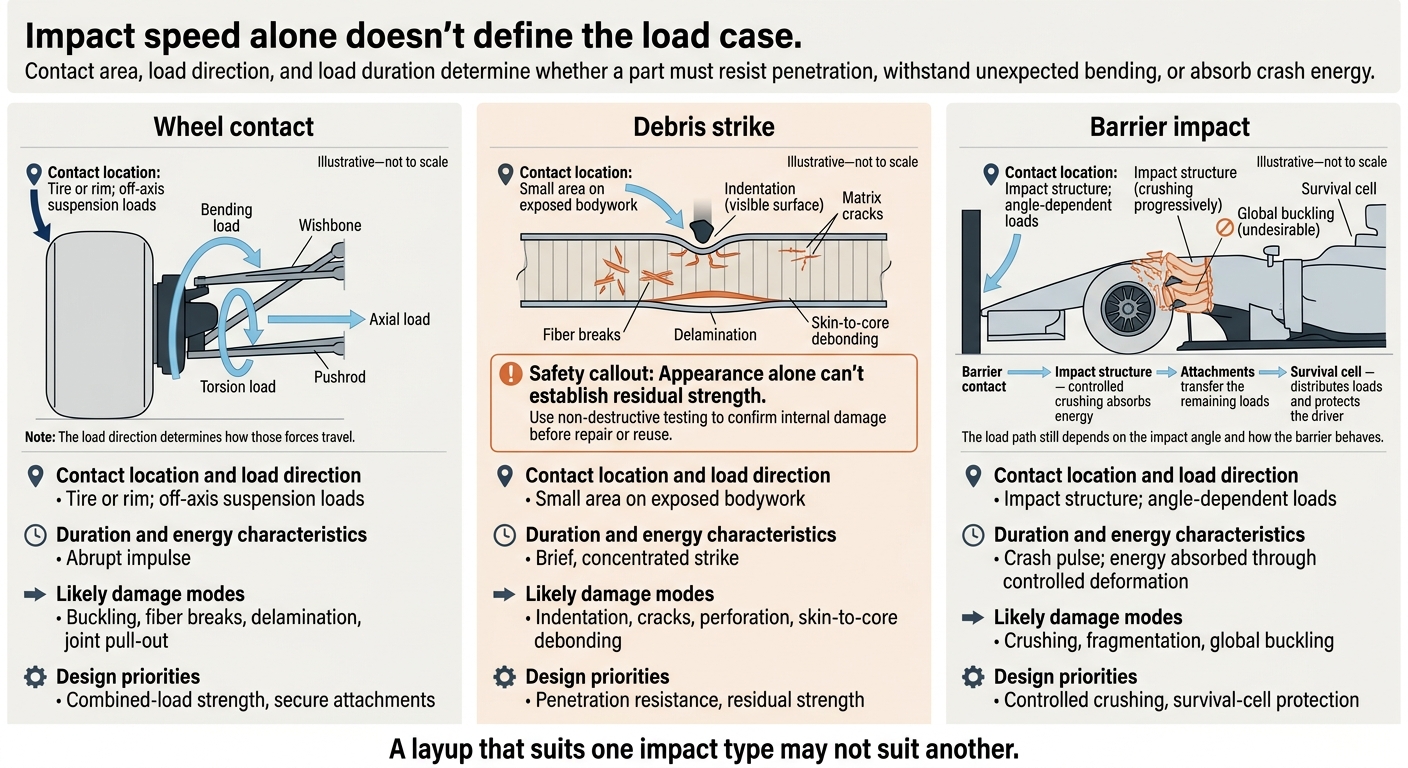
Impact speed alone doesn't define the load case. Contact area, load direction, and load duration determine whether a part must resist penetration, withstand unexpected bending, or absorb crash energy. A layup that suits one impact type may not suit another.
| Impact condition | Contact location and load direction | Duration and energy characteristics | Likely damage modes | Design priorities |
|---|---|---|---|---|
| Wheel contact | Tire or rim; off-axis suspension loads | Abrupt impulse | Buckling, fiber breaks, delamination, joint pull-out | Combined-load strength, secure attachments |
| Debris strike | Small area on exposed bodywork | Brief, concentrated strike | Indentation, cracks, perforation, skin-to-core debonding | Penetration resistance, residual strength |
| Barrier impact | Impact structure; angle-dependent loads | Crash pulse; energy absorbed through controlled deformation | Crushing, fragmentation, global buckling | Controlled crushing, survival-cell protection |
Wheel contact places the greatest focus on structural strength. Debris strikes and barrier impacts shift the priority from stiffness toward damage control and crush management.
How Wheel Contact Loads the Suspension
Wheel contact sends bending, torsion, and axial loads through the hub and upright, then into the wishbones and pushrod. The load direction determines how those forces travel. A member designed for normal running can buckle or splinter under this sudden impulse.
Debris Strikes and Hidden Damage
A small strike can leave hidden matrix cracks, fiber breaks, or delamination. Severe strikes can perforate a panel, while skin-to-core debonding reduces the stiffness of sandwich bodywork. Appearance alone can't establish residual strength.
Use non-destructive testing to confirm internal damage before repair or reuse.
Barrier Loads and Crash Energy
Barrier impacts shift the goal from resisting damage to managing deformation. A crash structure must crush progressively rather than stay rigid or fail through global buckling. Its attachments must carry the resulting loads into the survival cell.
Simplified barrier-impact load path:
Barrier contact
      ↓
Impact structure  -  controlled crushing absorbs energy
      ↓
Attachments  -  transfer the remaining loads
      ↓
Survival cell  -  distributes loads and protects the driver
The load path still depends on the impact angle and how the barrier behaves.
Resin Toughness and Crack Control
Carbon fibers carry loads mainly along their length. After an impact, the resin matrix helps determine whether damage stays local or spreads between plies. It transfers shear between fibers and plies, shares loads around broken fibers, and supports fibers against micro-buckling in compression.
Interlaminar fracture toughness, or delamination resistance, measures resistance to delamination growth - not fiber tensile strength. Even strong fibers can produce a damage-prone laminate if cracks spread easily between layers. That makes crack deflection and delamination resistance the next design targets.
Toughened Epoxies and Interleaves
Toughened epoxies use rubber or thermoplastic particles to blunt cracks and absorb energy. Thin, ductile interleaves between plies can also slow crack growth. But their effect depends on resin compatibility and the cure cycle. Adding a toughening layer doesn't automatically improve performance.
Consolidation needs close control. Resin-rich pockets at ply terminations add mass and create brittle zones without guaranteeing more toughness.
Processing Quality and Resin Limits
Cure temperature, pressure, and consolidation must match the resin system. High-quality prepreg consolidation often uses 7–10 bar (102–145 psi) of autoclave pressure, but pressure alone doesn't guarantee quality. Prepreg storage, moisture, and fiber–resin bonding also need control. Voids concentrate stress and provide starting points for cracks, reducing the gains from toughening.
Toughening can bring trade-offs in mass, stiffness, heat resistance, and processing complexity. Thermoplastic particles and interleaves toughen epoxy; they don't turn the part into a thermoplastic composite. Tough resin limits crack growth, but crash energy management still depends on how the structure crushes.
Controlled Crushing and Low-Mass Design
Progressive Crushing in Crash Structures
Once resin limits crack growth, geometry determines whether a part crushes progressively or fails as a column. A crash structure must begin a controlled crush, not act like a rigid beam. Chamfers, notches, or holes concentrate stress locally, starting the crush at a chosen point.
As the crush front moves through the part, fiber fracture, matrix cracking, delamination, and fragmentation dissipate energy. Fiber angles and geometry must guide that process rather than allow rigid-column buckling. Adding ±45° plies can help in some cases, but they don't guarantee stable crushing. Reinforcement is about controlling the crush - not just adding strength.
Front, side, and rear impact structures are sacrificial. The survival cell, by contrast, must preserve the driver's protected space. Engineers need to compare simulated crush behavior with physical tests, checking both the initial force peak and sustained energy absorption.
Choosing Reinforcement Without Excess Weight
Once the crush mode is defined, add carbon only where it improves that behavior. Before adding material, check impact direction, energy, stiffness, allowable deformation, residual strength, inspection access, repeatability, and replacement time.
Compression-after-impact testing measures retained compressive strength. Ultrasonic C-scans or thermography help locate hidden damage. Appearance or retained stiffness alone cannot establish that a struck component is safe to reuse.
The right fix depends on what the part needs: more penetration resistance, better crush control, or both.
| Design change | Benefit | Mass or space cost | Main limit |
|---|---|---|---|
| Added plies | Greater ultimate strength | More mass and thickness | May not prevent delamination or stabilize crushing |
| Revised fiber angles | Improved shear and impact tolerance | No added mass | Can reduce longitudinal stiffness and axial capacity |
| Toughened resin or interleaves | Slower crack growth between plies | Low added mass; slight thickness increase | Can reduce heat resistance |
| Geometry changes | More controlled crush initiation and progression | Can require more space | Sensitive to impact direction |
More plies do not guarantee better impact performance.
Conclusion: Match the Layup to the Part
Match fiber direction, resin toughness, and geometry to the part's load case. Survival-cell protection, suspension stiffness, and crash structures require different layups; no single carbon stack delivers all three at minimum mass.
FAQs
How do teams test layups for different impacts?
Teams test F1 carbon-fiber layups using finite element analysis (FEA) and test rigs that reproduce impact loads, directions, contact areas, and mounting conditions. They measure strain and displacement to check whether the models match the test results.
Static loads are applied in steps to check linearity and hysteresis. Teams also repeat tests across production batches and assess how changes in ply thickness, fiber orientation, and stiffness affect the results. When deflection or crack control falls short of targets, they adjust the layups, inserts, or reinforced load paths [1].
Can impact-damaged carbon fiber be safely repaired?
Yes, but repairs are strictly regulated to protect structural integrity. After curb strikes or debris hits, mechanics check for damage through visual inspections and stiffness tests. Parts with compromised structural integrity are usually replaced rather than repaired [1].
Teams log every repair, along with retest evidence, in a change-control system. Each part’s repair history can be traced by serial number to show FIA scrutineers that it meets the rules [1].
How do engineers balance crash protection and weight?
Engineers combine advanced materials with simulation-driven design to keep structures strong without adding unnecessary weight. They align carbon fiber layers with the main load paths and use foam or honeycomb cores to cut mass [1].
Titanium or high-strength aluminum inserts reinforce selected areas, so the entire structure doesn’t need to be thicker. CAD and finite element analysis help fine-tune thickness and shape. A 10–20% stiffness buffer allows for manufacturing variability and material aging [1].