How F1 Teams Test Telemetry Systems
Breaks down the five-stage workflow F1 teams use to bench-test sensors, validate radio links, correlate data, and ensure FIA compliance.
F1 telemetry only matters if the data is right, on time, and legal. In simple terms, teams test the full data path: sensors, wiring, ECU, radio link, pit-wall systems, and post-run checks.
Here’s the short version:
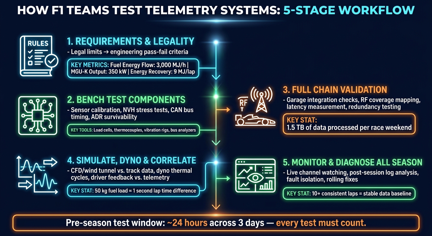
- I’d sum the process up as five checks:
- define legal and engineering limits
- bench-test sensors and electronics
- verify the full car-to-pit data link
- compare live data with sim and dyno traces
- monitor faults all season
- Teams are checking for accuracy, delay, dropout risk, and FIA rule compliance
- Some channels are tied to hard 2026 limits, like:
- MGU-K output: 350 kW
- Energy recovery: 9 MJ per lap
- Fuel energy flow: 3,000 MJ/h
- Trackside systems also need to handle volume. Over a race weekend, teams may process about 1.5 TB of data
- Pre-season test time is limited to about 24 hours across 3 days, so each test has to be planned well
What stands out to me is that teams don’t just ask, “Is the sensor working?” They ask:
- Does it stay accurate under heat and vibration?
- Does the signal reach the pit wall with low delay?
- Does the whole chain still work when the car is at speed?
- Does the FIA reference agree with the team’s own reading?
A simple way to look at it: bench tests check parts, track tests check the link, and correlation checks whether the data matches what the car is doing.
| Stage | What I’d check | Main failure risk |
|---|---|---|
| Requirements | Legal limits and pass/fail rules | Non-compliant channels |
| Bench testing | Sensor drift, wiring faults, bus timing | Bad readings before install |
| Car/track validation | RF coverage, delay, dropouts | Lost or late live data |
| Correlation | Sim, dyno, and track agreement | Data that looks right but isn’t |
| Session monitoring | Flatlines, packet loss, corner-specific faults | Problems that show up later |
If you want the core takeaway in one line, it’s this: F1 teams make telemetry race-ready by testing every step of the chain, then checking it again under load, at speed, and through the full season.
F1 Telemetry Testing: 5-Stage Workflow Explained
Former F1 Data Engineer Explains Race Telemetry | MoTeC [#TECHTALK]
sbb-itb-7c68254
1. Define requirements, legality, and pass-fail criteria
Before any hardware goes on the car, engineers turn sporting and technical goals into clear pass-fail limits. Those limits become the yardstick for every bench test and every trackside check that comes after.
Translate FIA rules into engineering limits

The FIA technical rules define the legal envelope for the Standard ECU (SEU). That system controls MGU-K power, active aero, and brake-by-wire. So the first job is simple: convert the rulebook into hard engineering limits.
If the car has any inbound communication capability beyond what the FIA allows, that's a legality failure. No gray area.
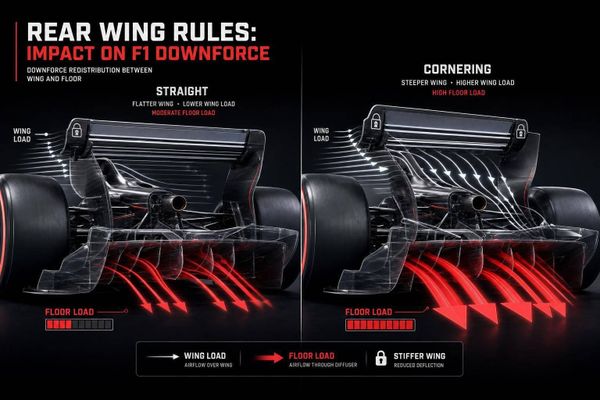
For 2026, teams also check that wing positions change only inside approved activation zones. That means continuous position reporting becomes a channel-specific pass-fail item. And for FIA-mandated channels, teams calibrate internal sensors against homologated references, not against in-house models.
Set measurable targets for each telemetry channel
Next, teams turn those legal limits into acceptance criteria for each channel:
| Channel | Limit / Metric | Testing Pass-Fail Focus |
|---|---|---|
| Fuel Energy Flow | 3,000 megajoules per hour | Zero tolerance for exceeding the FIA fuel flow meter reading |
| MGU-K Output | 350 kilowatts | Internal sensor must match the FIA-homologated measurement |
| Energy Recovery | 9 megajoules per lap | State-of-charge tracking over a full lap |
| Active Aero Position | Approved wing positions | Continuous reporting within GPS-verified activation zones |
| Boost Deployment | 150 kilowatts over ICE output | Deployment stays within the defined energy envelope |
| Sampling Rate (Power) | Up to 15 MS/s | Captures high-frequency inverter and motor behavior |
That table covers the rule-driven channels. But teams don't stop there.
They also set in-house limits for latency, synchronization, and allowed error bands so time-stamped traces line up with simulation outputs and control-system logs. If one log says the car deployed energy at a given instant, the rest of the data has to agree. Otherwise, the trace can't be trusted.
Physics-based validation tools help here too. The Project Apex system, used during the 2026 Canadian Grand Prix, is one example. It checks live data against deterministic models of tire degradation and ERS state transitions to flag error bands that should be physically impossible.
"When the reported energy state is inconsistent with the measured power output, or when thermal readings don't match deployment curves - something is wrong." - Timothy D. Harmon, CISSP, Lead Enterprise Architect, Project Apex
Once those limits are locked in, teams can bench-test each sensor, cable, and ECU against them.
2. Bench-test sensors, wiring, and data acquisition hardware
Bench testing checks each sensor, cable, and DAQ unit against pass-fail limits before anything goes on the car. Put simply, it turns the rulebook into a set of hard shop-floor tests.
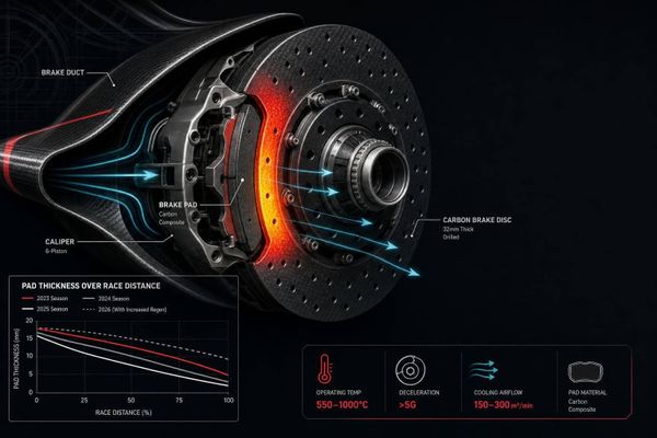
Calibrate sensors with controlled loads and temperatures
Teams apply known loads with calibrated transducers and load cells, then verify linearity and repeatability across the full operating range. They run thermal calibration at the same time, using thermal probes, thermocouples, and infrared cameras to map how readings drift as temperatures change.
That matters because a sensor can look fine at room temperature and still go off once heat builds up. So the target isn't just accuracy on paper. The sensor has to stay steady across the conditions it will see in use.
Accuracy also isn't the whole story. Wiring and electronics still need to hold up under race loads.
Stress-test electronics and network communications
Engineers put wiring looms, connectors, and DAQ units through noise, vibration, and harshness (NVH) testing. They use strain gauges and acceleration transducers to spot mechanical fatigue and resonance issues early. High-speed power analyzers sampling at up to 15 MS/s then check signal integrity through the full wiring and DAQ chain.
The CAN bus gets its own set of checks. It has to arbitrate in a predictable way and keep timing under load, with messages arriving without jitter or loss. Bus-load tests push traffic higher to confirm that timing stays stable.
| Test Category | Tools Used | Key Metrics |
|---|---|---|
| Calibration Tests | Multi-component transducers, load cells, thermocouples, infrared cameras | Drift, repeatability, reference instrument alignment |
| Communication Tests | Bus analyzers, packet monitors | Packet integrity, bus load, latency |
| Environmental Tests | Vibration rigs, thermal cyclers | Fatigue life, thermal cycling, vibration resistance |
The ADR is checked on its own because crash survivability matters more than live telemetry. The Accident Data Recorder (ADR) gets separate bench tests because it must preserve crash data on its own power and memory. If it fails structural or power-stability checks at the bench, it does not move forward until the issue is fixed.
Once those bench checks pass, the team can validate the full telemetry chain on the car.
3. Validate the full telemetry chain on the car and at the track
Once each part clears bench testing, teams still need to prove the whole telemetry chain works in the car and across the radio link.
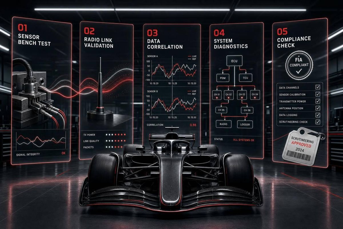
Run garage integration checks before the car leaves the pit lane
The first job is a structured power-on sequence in the garage. Engineers verify that the SECU reads every signal the right way before the car even rolls out. On the pit-wall display, they check each mandated channel in real time, including fuel flow, MGU-K power, gear, and throttle.
They also test rotary switches and buttons against their assigned SECU maps. That confirms the driver’s inputs trigger the expected responses for deployment, differential, and aero settings. Before the car moves, team sensors are also cross-checked against homologated references.
Once the signal map looks clean in the garage, engineers repeat those checks with the car in motion.
Measure RF coverage, latency, and dropout behavior on track
Installation laps and shakedowns are where teams map RF weak spots. As the car circulates, engineers watch the RF link and log signal strength, throughput, and dropout points against the circuit layout. It’s a bit like checking cell service in a tunnel: some areas are fine, others are a mess. Walls and trackside structures can create dead zones and reflections, and tight circuits like Monaco are especially hard to manage.
Latency gets measured by comparing a known physical event, such as a gear shift, with the moment it shows up on the pit-wall display. At the same time, engineers test backup paths so they know what happens if the primary link drops.
Those coverage maps help teams confirm whether the pit wall can still receive clean data in race conditions.
Test trackside receivers and data infrastructure under session loads
Practice sessions also act as a load test for the trackside data setup. Antennas, receivers, networking hardware, and server pipelines all run under full session demand. Over a race weekend, teams process about 1.5 TB of data.
| Test Type | Purpose | Typical Timing |
|---|---|---|
| Coverage Mapping | Identify weak signal areas and dead zones around the circuit | Shakedown / FP1 |
| Latency Testing | Measure delay between car events and pit-wall display | Installation Laps |
| Interference Checks | Assess how walls and structures affect signal integrity | Circuit-specific |
| Redundancy / Failover | Verify backup data paths if the primary radio link is interrupted | Pre-season / Reliability Stints |
Pre-season testing gives teams about 24 hours across three days, which makes it the main chance to run these checks in sequence.
4. Correlate telemetry through simulation, dyno work, and live running
Bench testing shows that a sensor turns on and sends data. Correlation checks something more important: whether that data still lines up with what the car is actually doing once it’s moving.
That’s why correlation sits between a working telemetry stack and race data a team can trust. It tests whether the signal still reflects reality under speed, load, heat, and vibration, not just in a calm garage setup.
Compare telemetry traces with simulator and dyno expectations
Teams close the loop by lining up CFD, wind tunnel, simulator, and track data. If those sources tell the same story, engineers can trust the picture. If they don’t, they start digging.
On the dyno, engineers put the power unit and gearbox through thermal and load cycles while tracking channels such as fuel mass flow, MGU-K torque, and vibration harmonics.
A 50 kg fuel-load swing can account for about one second of lap time. That matters a lot during correlation. If a simulator run assumes a lighter car but the live track run carries more fuel, the traces can drift apart for a perfectly normal reason. Without that context, a healthy telemetry channel can look wrong when it isn’t.
Use driver feedback and regression testing to confirm signal quality
Once the model and hardware line up, teams still need one more check: the driver.
Engineers compare radio feedback with telemetry all the time. They look at brake traces, steering inputs, ride metrics, and tire temperatures to see whether the data matches what the driver feels in the cockpit.
If the driver reports a balance issue and telemetry doesn’t show it, that can point to a flatlining sensor or a gap in the model. When driver feedback and telemetry disagree, engineers have to work out where the mismatch comes from:
- the car
- the sensor
- the model
After any hardware or software update, teams repeat set reference laps to make sure nothing has slipped. Long-run consistency is a strong signal-quality check. 10+ laps within a few tenths usually point to stable data and a car that’s behaving the same way lap after lap. Those laps then serve as the baseline for live monitoring.
Match each test environment to its purpose
Each test environment answers a different question, so teams don’t treat them the same way.
| Environment | Primary Objectives | Typical Channels Checked | Risks Uncovered |
|---|---|---|---|
| Simulator | Setup optimization; driver-in-the-loop feel; aero map validation | Virtual steering/pedal inputs; modeled aero loads | Model inaccuracies; driver handling miscorrelation |
| Dyno | Power unit and gearbox reliability; energy deployment maps | Fuel mass flow; MGU-K torque; thermal cycles | Mechanical fatigue; cooling inefficiencies |
| Pre-Season Testing | Aero correlation; tire model validation; system shakedown | Aero correlation channels; tire model inputs | CFD/wind tunnel miscorrelation; sensor calibration errors |
| Race Weekend | Regulatory compliance; live strategy; reliability monitoring | FIA mandatory channels; ERS deployment | Regulatory violations; environmental signal noise |
5. Monitor, diagnose, and improve telemetry systems through the season
Correlation shows the system worked at one point in time. Live running shows whether it still works when the season starts piling on stress.
That matters because telemetry systems don’t stay frozen. Parts drift. Track conditions shift. New upgrades can introduce faults in places that were fine a week earlier. So after bench checks, track tests, and correlation work, live running becomes the last layer of validation.
Track live system health during every session
Race weekends have a way of surfacing faults you didn’t see before, which is why telemetry stays under live scrutiny in every session.
While the car is running, engineers watch live channels for flatlines, outliers, and dropouts. They’re not just watching for weird signals out of curiosity. They’re making sure the system is still behaving under pressure, lap after lap.
Live monitoring also helps keep the car within legal limits across every session of the season. In motorsport, that line matters. A small data issue can turn into a compliance problem fast.
Review logs and isolate root causes after each run
Once the session ends, the work changes. During the run, engineers watch. After the run, they diagnose.
Scripts scan logs for missing packets, timestamp jumps, noise, and outliers. Teams use in-house code to strip out race noise and isolate the fault source. If dropouts keep showing up at the same corner, engineers tend to suspect RF shadowing. If the issue appears at random, wiring or sensors are usually the first place they look.
For position errors, teams fuse GNSS and IMU data to keep location tracking stable during short outages. They also cross-check proprietary sensor readings against FIA-homologated sensors. For compliance, the FIA reading is treated as definitive.
From there, each finding turns into action:
- Swap the sensor
- Inspect the harness
- Reposition the receiver
- Patch the software
Those fixes go straight into the next session, which is how teams keep the system race-ready instead of letting small faults pile up.
Conclusion: The testing workflow that makes telemetry race-ready
Teams build reliable telemetry in layers. They turn regulations into hard limits, bench-test each component, validate the full chain on the car and trackside, correlate signals against simulator and track data, and keep watching live through every session of the season.
Each layer catches something the previous one can miss. That loop is what keeps every link in the telemetry chain dependable from first rollout to the final lap.
FAQs
Why isn’t bench testing enough?
Bench testing only gets you so far. It can't recreate the harsh, fast-changing conditions of a race track.
A sensor might look perfectly calibrated in a controlled setting. But that same sensor still has to perform at high speed, under heavy vibration, and through sharp swings in temperature and humidity.
On-track testing is where teams see what happens outside the lab. It lets them compare simulation data with behavior on the car and check accuracy when extra variables come into play, like wind, traffic, and tire degradation. It also helps confirm FIA compliance.
How do teams know telemetry is FIA-compliant?
Teams use the FIA-mandated Standard ECU to handle data transmission and give the FIA direct oversight. That setup matters because it lets the governing body keep a close eye on what the car is doing, not just after a session, but as it happens.
The FIA monitors telemetry in real time through a direct link to each team’s data center. It checks key channels such as fuel flow and energy deployment, which helps officials spot any rule breaches right away instead of piecing things together later.
Before each season, the FIA also reviews team software. On top of that, it requires sensor calibration to be traceable to standardized units. In plain terms, the numbers teams report need to come from sensors that have been checked against the same measurement standards, helping keep the data accurate and within the rules.
What causes telemetry dropouts during a session?
Telemetry dropouts and delays usually happen for a few common reasons.
One big cause is signal interference. Another is network congestion. Limited bandwidth during wireless transfer from the car to trackside servers can also slow things down or cut the feed for a moment. On top of that, hardware problems, like poorly machined sensor mounts or failed components, can interrupt the flow of data.
The trouble doesn't always stop at the car, either. Bottlenecks can show up between trackside systems, factory headquarters, and cloud platforms. That gets tougher at flyaway races, where longer distances add more latency.
To cut the risk, teams use shielding, place sensors with care, and rely on redundant backup systems.