Brake-by-Wire in F1: Guide to ERS Brake Blending
How F1 brake-by-wire blends MGU‑K regeneration with rear friction brakes under 2026 rules, and why stable braking trumps max energy recovery.
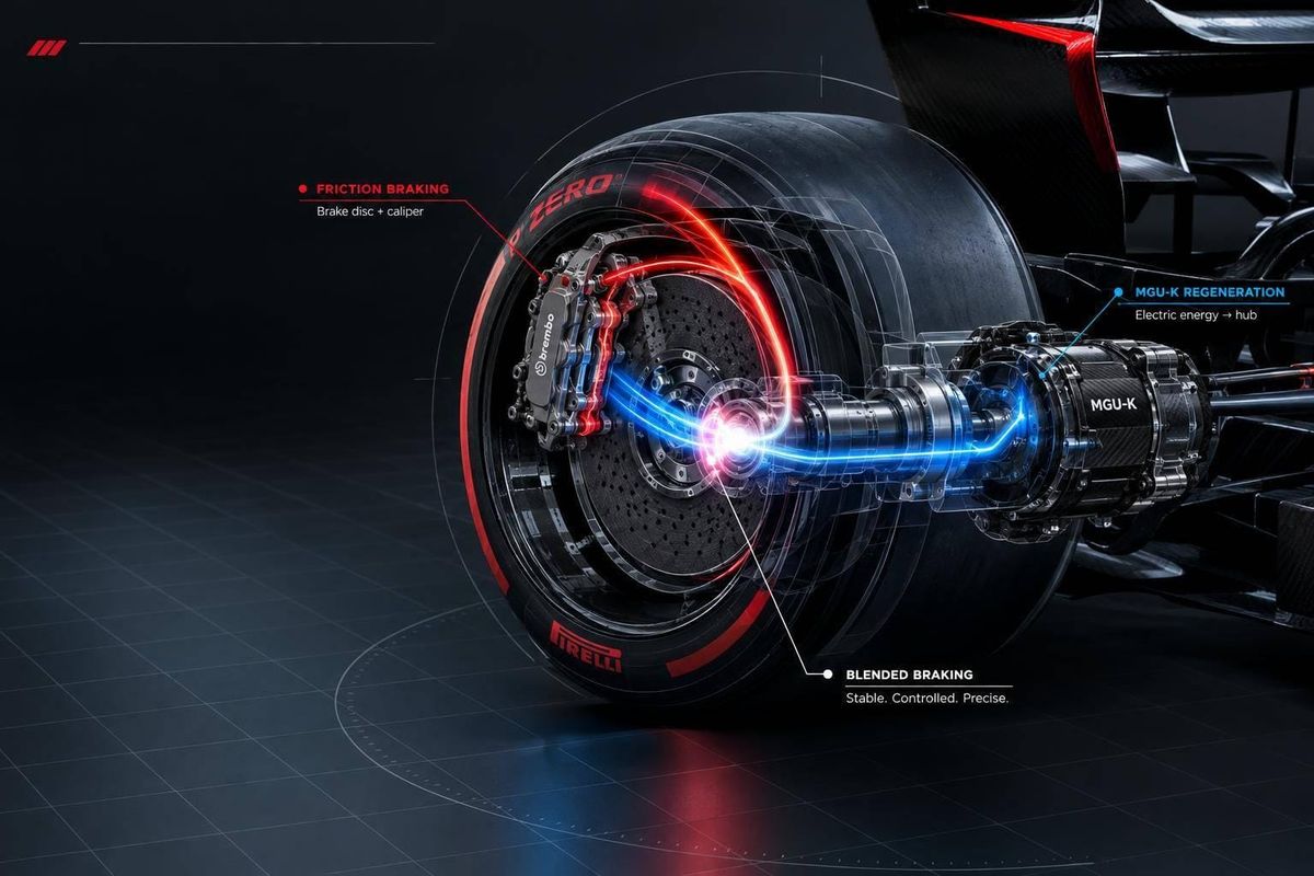
F1 brake-by-wire blends rear friction braking with energy recovery so one pedal delivers predictable braking. I think of it as torque substitution: when MGU-K recovery drops, rear friction brakes fill the gap within grip and hardware limits - not add extra stopping power.
Here’s what matters:
- Four torque sources: front friction brakes, rear friction brakes, MGU-K regeneration, and engine braking.
- 2026 limits: the MGU-K has a 350 kW electrical output cap and a separate 500 N·m torque limit referenced to crankshaft speed. Neither guarantees a fixed share of braking.
- Changing conditions: battery charge, heat, speed, and driver settings affect the rear blend. Automatic wheel-slip control is not allowed.
- Setup and safety: qualifying favors timed-lap preparation; races demand repeatable braking and heat control. Hydraulic fallback must remain available without MGU-K assistance.
My takeaway: <u>judge the blend by stopping control, not energy recovered alone.</u> More harvesting is no win if rear stability, brake temperatures, or corner-exit performance suffer.
How MGU-K Recovery and Friction Brakes Work Together
From Pedal Input to Rear Braking Torque
The rear brake-by-wire controller requests regenerative torque from the MGU-K, then uses rear hydraulic pressure to meet the rest of the braking demand. Engine braking is mapped separately in the power unit. Rear friction brakes work as part of the blend - not just as a backup.
Driver brake pedal
  ├─ Hydraulic front circuit → Front caliper torque
  └─ Rear braking demand → Rear brake-by-wire controller
                             ├─ MGU-K request → Regenerative torque
                             └─ Pressure request → Rear friction torque

Separate power-unit calibration → Engine-braking torque
                                  ↓
Total rear-axle braking torque =
regenerative torque + rear friction torque + engine-braking torque
Hypothetical torque example - not measured F1 data: A 3,000 N·m rear-axle demand could comprise 1,400 N·m of regeneration, 300 N·m of engine braking, and 1,300 N·m of rear friction braking. If regeneration falls to 900 N·m, friction braking must rise to 1,800 N·m to maintain the total, provided grip and hardware limits allow.
Limits on Regenerative Braking in 2026
The FIA’s 2026 rules cap MGU-K electrical output at 350 kW, but that isn’t a fixed braking-torque limit. Mechanical torque has a separate 500 N·m limit, referenced to crankshaft speed. Because the MGU-K normally has a mechanical link to the crankshaft, engine speed, gear selection, and drivetrain ratios constrain its operating window. A protective torque-limiting device can briefly relax the speed-ratio limit to shield components from torque spikes. It isn’t a performance feature.
The harvesting allowance is up to 8.5 MJ per lap. That limit drops to 8 MJ at events where the governing body determines that the circuit’s maximum possible harvesting under braking and partial load is no more than 8 MJ. A separate provision allows up to 0.5 MJ of additional harvesting under specified conditions.
These allowances don’t guarantee that the car will recover that much energy. Harvested energy is measured at the CU-K high-voltage DC bus, not as usable battery energy. Battery charge acceptance, state of charge, temperatures, rotational speed, torque limits, losses, and deployment all affect how much energy can be recovered and retained.
4 Sources of Braking Torque
All three rear-axle braking sources rely on the same rear-tire grip. Swapping regeneration for caliper torque doesn’t add stopping capacity. And during corner entry, the tires also need grip to produce cornering force, leaving less available for braking. The blend is torque substitution, not a fixed electric-versus-friction split.
| System | Primary function | Main limitation | Effect on setup |
|---|---|---|---|
| Front friction brakes | Provide front-axle braking torque | Heat, wear, and available tire grip | Front balance and tire loading |
| Rear friction brakes | Supply remaining rear braking demand | Heat, wear, and available tire grip | Rear stability and thermal management |
| MGU-K regeneration | Recover energy while resisting rotation | Battery, speed, torque, power, and energy limits | Available regenerative contribution |
| Engine braking | Produce resisting torque through the power unit | Operating state and calibration | Corner-entry stability and rear response |
Software adjusts that mix in real time as speed, grip, and battery state change.
sbb-itb-7c68254
Brake by Wire system in F1
How Software Controls Brake Blending
F1 Brake-by-Wire: How Rear Brake Blending Changes
Inputs That Shape the Rear Brake Blend
With the four torque sources defined, the next step is understanding how software combines them lap by lap. The rear brake blend depends on pedal input, speed, state of charge, temperature, and driver setting. Pedal pressure, travel, and application rate set the braking demand. Rear-wheel speed, MGU-K capability, and the battery’s ability to accept charge limit what the system can deliver. Temperature and hydraulic-pressure limits protect the system. Public rules define its architecture, but not teams’ transition maps.
Wheel speed, steering angle, and lateral load estimates need context: recording a signal does not prove that it controls the blend. The system must preserve the driver’s braking request without taking over wheel-slip control.
Brake Application, Trail Braking, and Release
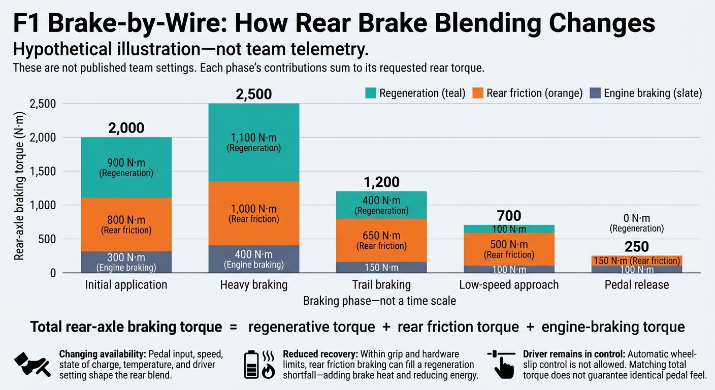
The blend also changes through each pedal phase. At turn-in, software favors stable rear torque. As load and speed fall, calibrated shifts toward friction and engine braking help manage lock-up and yaw risk without automatic wheel-slip control. MGU-K braking faces tighter limits at low speed. As the driver releases the pedal, the controller reduces rear torque smoothly to prevent an abrupt step.
Hypothetical illustration - not team telemetry. All figures are rear-axle torque in N·m. Each row’s contributions sum to its requested total; these are not published team settings.
| Braking phase | Requested rear torque | Regeneration | Rear friction | Engine braking |
|---|---|---|---|---|
| Initial application | 2,000 | 900 | 800 | 300 |
| Heavy braking | 2,500 | 1,100 | 1,000 | 400 |
| Trail braking | 1,200 | 400 | 650 | 150 |
| Low-speed approach | 700 | 100 | 500 | 100 |
| Pedal release | 250 | 0 | 150 | 100 |
Reduced Recovery and Hydraulic Fallback
When energy recovery drops, the system leans more on hydraulics. A battery that cannot accept as much charge, or components running too hot, can reduce recovery without a brake-by-wire fault. Within system limits, rear friction braking can fill the gap. That means more heat in the discs and pads, and less energy harvested.
Matching total torque does not guarantee the same feel. Hydraulic response, torque-transition rate, tire temperature, and axle loading still matter. A steady torque trace alone does not prove unchanged behavior; compare temperature, pressure, load, and transition rate too.
One pedal operates separate front and rear hydraulic circuits through two master cylinders. The FIA’s cited 2026 rules require at least 2,500 N·m of braking torque at each rear wheel, without power-unit or MGU-K assistance, at no more than 150 barG caliper pressure. A pedal-connected hydraulic source must remain available when powered rear control is disabled. During powered operation, rear-circuit pressure cannot exceed 1.2 times the rear master-cylinder pressure at that same moment. These rules preserve braking capability, but they do not guarantee identical pedal travel, balance, recovery, or lap time.
Brake Setup for Qualifying and Races
Once blend behavior is defined, setup choices determine how much of that performance the car can use in qualifying or across a race stint.
Qualifying and Race Priorities
Qualifying prep starts on the out-lap: get tires and brakes into their working range, then set battery charge for the timed lap. Recovery still matters. The battery needs room to accept energy, not just enough charge to deploy. Traffic or rain can disrupt the plan, so the blend must remain predictable.
| Parameter | Qualifying priority | Race priority |
|---|---|---|
| Energy strategy | Prepare charge and deployment for a timed lap | Balance recovery and deployment over successive laps |
| Rear blend | Optimize entry performance within the expected operating window | Keep response predictable as conditions change |
| Friction brakes | Reach effective temperatures for the run | Manage repeated thermal loads and wear |
| Brake balance | Match available grip and corner demands | Adjust for fuel burn, tire wear, and changing grip |
| Torque transitions | Maintain stability while pursuing lap time | Maintain stability and repeatability |
Driver Settings and Engineering Feedback
Drivers put these priorities into practice through brake balance, migration, and engine-brake maps.
Brake balance sets the starting front-to-rear distribution. Brake migration changes that distribution through the stop. Engine-braking settings control the power unit’s resistance at the rear axle, while permitted energy-management modes set recovery and deployment targets. Together, they shape rear-axle torque demand and how the blend meets it. Drivers select calibrated settings - not a fixed regenerative split.
Engineers build those calibrations, then compare driver reports of locking, rotation, and pedal feel against pressure, wheel-speed, torque, and temperature traces. Driver-selectable adjustments are separate from map rewrites or hardware changes. Parc fermé limits major setup changes from the first qualifying pit-lane exit to the race formation lap; brake bleeding and FIA-approved weather changes remain allowed.
Brake Setup Trade-Offs and Common Symptoms
Charge headroom - the battery’s unused capacity - matters as much as starting charge. Too little headroom limits recovery; too little stored energy limits deployment. More friction braking adds thermal load. Moving braking rearward can help the car rotate, but it can also reduce stability. A race setup must handle repeated stops, component limits, and changing grip rather than pursue maximum recovery at every corner.
The table connects symptoms in driver feedback and telemetry with setup areas to check.
| Symptom | Areas to investigate |
|---|---|
| Rear locking on entry | Brake balance, blend transitions, tire grip, driver input |
| Instability during trail braking | Migration, engine braking, torque release, rear-axle loading |
| Inconsistent pedal feel | Hydraulic behavior, actuator response, blend transitions |
| Excessive rear-brake temperature | Friction share, cooling, reduced recovery |
| Insufficient harvesting | Charge acceptance, MGU-K limits, strategy, braking opportunities |
| Battery reaches charge limit early | Starting charge, recovery targets, deployment strategy |
Treat these as starting points for investigation, not diagnoses. Compare the same braking zone across laps, checking entry speed, fuel load, tire condition, battery charge, recovered energy, and corner-exit speed. A strong braking trace alone does not prove a lap-time gain.
Conclusion: Balancing Braking, Recovery, and Stability
Software manages the braking blend lap by lap, but the driver should still feel one consistent brake. Brake blending combines changing rear-axle torque sources into a steady pedal response.
The 2026 rules give the MGU-K more electrical power, leaving software with more work to keep rear braking predictable.
Mechanical fallback is still mandatory: the rear circuit must provide braking without MGU-K assistance.
The goal is stable stopping performance, not maximum energy harvesting.
FAQs
Why isn't F1 brake-by-wire considered ABS?
F1 brake-by-wire blends friction braking with energy recovery. It doesn’t prevent wheel lockup. The driver controls the braking inputs, while software adjusts rear hydraulic brake pressure based on the braking torque supplied by the MGU-K.
An anti-lock braking system (ABS), by contrast, automatically adjusts brake pressure to keep tires from sliding. F1 brake-by-wire does not offer that anti-lock assistance.
How does rain affect brake blending?
Rain reduces tire grip, limiting how much energy the Motor Generator Unit-Kinetic (MGU-K) can safely recover during braking. Aggressive electrical braking can lock the wheels on wet surfaces.
To keep the car stable, teams adjust their brake-by-wire software to favor friction brakes over MGU-K energy recovery. The software balances braking force, helping drivers work with less grip without upsetting the car.
Can more energy recovery hurt lap times?
Yes - if it isn’t managed correctly. Recovered braking energy can improve performance, but FIA limits require careful control of battery charge. Software must also balance friction braking with energy recovery through the MGU-K.
In 2026, up to 8.5 MJ per lap and 350 kW capability, subject to mode/override rules, make smooth, precise transitions between the two more important. Poor tuning can hurt acceleration or force drivers to use safer “lift-and-coast” approaches on energy-sensitive tracks.