How F1 Teams Process High-Heat Alloys
Step-by-step F1 guide from feedstock to release: alloy selection, forming route, heat treatment, machining, inspections and traceability.

For high-heat F1 parts, I start with the service loads and FIA rules - not just the alloy name. Then I check the full path from certified stock to an inspected, traceable part. Even titanium needs care: sustained exposure near 752°F (400°C) or above calls for validation.
Here’s the process I follow through this guide:
- Choose the alloy and feedstock: Match heat, fatigue, oxidation, and weight needs, then check certificates and material identity.
- Shape the part: Compare forging, investment casting, and metal powder printing by load path, geometry, waste, and inspection access.
- Control heat treatment and distortion: Use alloy-specific cycles, stress relief, and HIP where specified.
- Machine, inspect, and release: Check dimensions, surface condition, defects, and required properties against set limits.
My main takeaway: material approval is only the start. <u>The complete manufacturing record must support the part’s release.</u>
F1 Alloy Heat Treatment: Three Manufacturing Routes
How Formula 1 Pistons Are Made (I went to the factory)
sbb-itb-7c68254
2. Shape the Part: Forging, Casting, or Additive Manufacturing
Choose the route based on load path, geometry, quantity, material condition, and inspection access. This choice controls grain flow, porosity, and the finishing work left to do. Forging suits parts that need controlled grain flow. Casting and powder-bed fusion allow more complex shapes. Before committing to enclosed features, plan how you'll clean and inspect them.
| Route | Typical property potential* | Geometric freedom | Material waste | Internal features | Inspection needs |
|---|---|---|---|---|---|
| Forging | Can be favorable when grain flow aligns with the load path | Limited by die access and metal flow | Flash, trimming, and machining stock | Restricted; passages generally need later machining | Check laps, cracks, internal soundness, and grain structure |
| Investment casting | Depends on sound solidification and microstructure | Complex near-net shapes | Gates, risers, and finishing stock | Ceramic cores can form passages | Check shrinkage, inclusions, cracks, and core position |
| Powder-bed fusion | Depends on fusion quality, build direction, and post-processing | High, within support and build limits | Supports and finishing stock | Complex channels need powder-removal access | Check porosity, cracking, dimensions, and internal surfaces |
Final properties depend on the complete processing route and qualification - not the forming method alone.
Forge the Billet
Heat the billet within its alloy-specific working window. Prepare the dies with controlled temperature and suitable lubrication, then follow the qualified temperature, strain-rate, and reduction schedule. Reheat as needed, and align grain flow with key service loads where practical.
Trim the flash and inspect the forging before further processing. Poor metal flow can create laps. Unsuitable temperatures or deformation can cause cracks or an unwanted grain structure.
Investment-Cast the Shape
Make the wax pattern, add cores where needed, and build the ceramic shell with repeated slurry and stucco layers. Remove the pattern and fire the shell, then pour the alloy under controlled filling and cooling conditions.
Control feeding to limit shrinkage. Control filling and cooling to limit inclusions and cracking during solidification. Remove the shell and cores, trim gates and risers, and inspect the casting. Correct core position and complete core removal are needed for passages to match their intended shape.
Build the Part From Powder
Prepare the qualified powder, set the build orientation and supports, and load the build plate. Qualification must address how orientation and fusion quality affect porosity, directional properties, residual stress, and internal surface roughness. It must also confirm access for cleanup and inspection.
Build the part layer by layer and monitor fusion. Then remove supports and trapped powder before heat treatment.
Each route leaves residual stress and a risk of distortion. The next step addresses both through controlled heat treatment.
3. Heat-Treat the Part and Limit Distortion
Use Alloy-Specific Heat Treatments
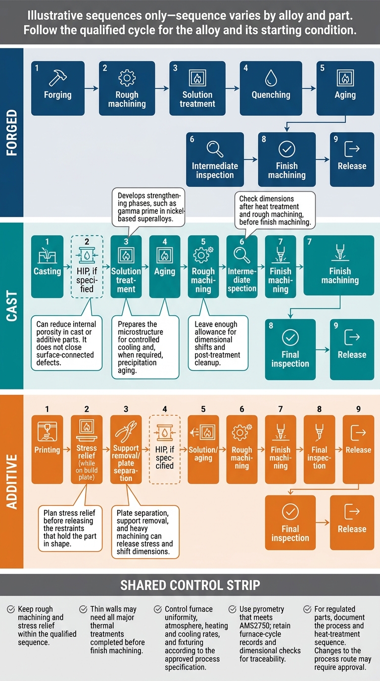
After forming, heat treatment builds strength and helps control distortion before finish machining. Follow the qualified cycle for the alloy and its starting condition. Solution treatment prepares the microstructure for controlled cooling and, when required, precipitation aging. Aging develops strengthening phases, such as gamma prime in nickel-based superalloys. This cycle prepares the part for rough machining and final inspection.
For cast or additive parts, hot isostatic pressing (HIP) can reduce internal porosity. Treat HIP as one step in the qualified process - not a fix for surface-connected defects, which it does not close.
Illustrative process-flow graphic - sequence varies by alloy and part:
FORGED
Forging → Rough machining → Solution treatment
→ Quenching → Aging → Intermediate inspection
→ Finish machining → Final inspection → Release

CAST
Casting → HIP, if specified → Solution treatment
→ Aging → Rough machining → Intermediate inspection
→ Finish machining → Final inspection → Release

ADDITIVE
Printing → Stress relief (while on build plate)
→ Support removal / plate separation → HIP, if specified
→ Solution/aging → Rough machining → Finish machining
→ Final inspection → Release
Keep rough machining and stress relief within the qualified sequence. Thin walls may need all major thermal treatments completed before finish machining.
Control Stress and Record Furnace Cycles
Plan stress relief before releasing the restraints that hold an additive part in shape. Plate separation, support removal, and heavy machining can release stress and shift dimensions. Leave enough machining allowance for those shifts and post-treatment cleanup. Check dimensions after heat treatment and rough machining, before starting finish machining.
Follow the approved process spec to control furnace uniformity, atmosphere, heating and cooling rates, and fixturing. Use pyrometry that meets AMS2750, and keep cycle records and dimensional checks for traceability.
For regulated parts, document the process and heat-treatment sequence. Changes to the process route may require approval.
4. Machine, Finish, and Inspect the Part
Machine and Finish Without Surface Damage
After heat treatment, final machining corrects distortion and brings the part to drawing dimensions. Allow for post-heat-treatment movement when planning cuts. The forged, cast, or printed shape is an intermediate part - not a finished component.
Plan machining and finishing to meet drawing tolerances and surface finish requirements. Before cutting begins, define controls for work hardening, surface damage, and distortion.
Check Dimensions, Defects, and Properties
Set acceptance criteria before machining starts. Dimensions alone don't determine acceptance. Define defect inspections and property checks in the technical specification before production begins.
Set inspection gates for the formed, heat-treated, and finished part stages. Check the near-net part against the planned machining allowance, then verify finished dimensions against the drawing.
Release the Part With Traceable Records
Use inspection results to decide whether the part meets the agreed acceptance criteria for release. Attach the final processing and inspection record to the part or batch. Before release, document every out-of-spec result and how it was resolved.
5. Conclusion: Check the Complete Manufacturing Route
Approve the full manufacturing route against the route card - not just the alloy. Base every process choice on part geometry, thermal load, fatigue load, and FIA rules.
Before installation, complete the release checklist: verify feedstock chemistry and identity; qualify the forming route; record furnace and stress-relief cycles; accept dimensions and surface finish; pass inspections; and attach full traceability records. Release the part only when its record matches its full manufacturing history.
FAQs
How do teams predict an alloy part’s race lifespan?
Teams use digital models of expected loads, temperatures, and duty cycles to predict how long an alloy part will last during a race. Once racing begins, engineers update those estimates by comparing live sensor data with pre-race baselines or digital twins. Predictive tools flag unusual readings, such as changes in temperature and pressure, so engineers can assess failure risks and adjust how the part is used before damage worsens.
How are hidden cooling channels inspected?
Teams typically use high-resolution industrial computed tomography (CT) scanning to inspect hidden cooling channels without damaging the part. The scan creates a detailed 3D model of the internal geometry, letting engineers check for manufacturing debris, blockages, structural defects, and dimensional accuracy.
Engineers often compare these scans with the original CAD designs to spot deviations that could reduce cooling performance or weaken the structure.
When must a manufacturing process be requalified?
In Formula 1, a process must be requalified when changes to technical specifications, materials, or manufacturing methods fall under FIA homologation requirements.
For critical systems like the Energy Recovery System, changes to design or assembly require updated technical documentation and new laboratory testing at FIA-recognized facilities. These checks confirm that the component meets performance, durability, and safety standards before it’s used in competition.