Study Summary: Composite Aero in Formula 1
The fastest F1 wings are tuned to bend in precise ways, balancing laminate lay-up, surface finish, manufacturability and FIA limits.
In Formula 1, a carbon-fiber wing is not just light - it is built to bend in planned ways. My takeaway is simple: lap time comes from balancing four things at once - laminate design, aero load, FIA deflection limits, and surface finish.
Here’s the article in plain terms:
- CFRP layout controls flex. Fiber direction, ply angle, and thickness decide whether a wing bends, twists, or stays stable.
- Static FIA tests do not show the full picture. A front wing may stay under the 20 mm test limit under a 100 kg load, yet still twist more under air load at speed.
- That twist can change performance. In the cited FSI results, tuned designs went from about 25.2 mm to 38.1 mm of load-driven deflection, while the rigid baseline stayed at 10.0 mm.
- Surface finish matters. Small flaws - pinholes, waviness, resin-rich spots, or exposed fibers - can disturb airflow and add drag.
- Build quality affects repeatability. If ply angles shift during draping or cleanup, the part may not flex the same way lap after lap.
- The full workflow is linked. Teams use FEA, CFD, FSI, virtual draping, wind-tunnel work, and track checks to match the model to the car.
If you want the shortest version: the fastest F1 aero parts are not just stiff or light - they are tuned to deform in a controlled way, stay inside the rules, and keep the same shape and surface quality over a race distance.
Why Is Carbon Fibre So Important In F1? Albert Fabrega's F1 TV Tech Talk Demo | Crypto.com

sbb-itb-7c68254
Material Behavior Under Load and Its Effect on Aero
Composite aero research looks at a simple but powerful idea: laminate design decides how aerodynamic load turns into flex. And that flex can change downforce, drag, and balance.
In F1, aero parts don’t stay perfectly still under load. They bend, twist, and shift shape. Those shape changes feed straight into car performance. The main lever here is the laminate layout. Ply orientation and thickness decide how the part moves when load builds.
How Ply Lay-Up, Fiber Direction, and Thickness Affect Flex
A typical F1 wing laminate uses a hybrid stack: woven carbon fabric on the outside and inside skins, with unidirectional (UD) plies placed between them. The woven layers add stiffness. The UD plies let engineers tune stiffness by direction.
That’s where lay-up starts to matter. By changing ply angles - most often 0° and ±45° - designers can stiffen one load path while still allowing twist somewhere else. It’s a bit like bracing one part of a ruler while letting the far end rotate.
Studies show the outer ends can twist back under load, reducing angle of attack at speed. That controlled flex is the whole game. A wing can have enough beam stiffness to pass the FIA’s static vertical load test while still staying more flexible in rotation.
There’s a catch, of course: mass. Adding plies to one area increases local stiffness, but it also adds weight. So engineers use finite element analysis to tune thickness element by element across the structure. Lay-up can also shift fiber angles, which means the models need to account for ply misalignment.
What FSI Studies Show About Wing Deflection
Once the lay-up is locked in, FSI shows whether that stiffness profile helps the aero package or works against it. It links structural deflection to pressure changes, so engineers can see how a wing’s shape change affects downforce. The numbers below show the difference between a rigid baseline and tuned laminates:
| Configuration | FIA Static Displacement | Load-Induced Deflection | Performance Impact |
|---|---|---|---|
| Baseline | 10.0 mm | 10.0 mm | Rigid behavior; no aero-elastic gain |
| Optimized 1 | 19.9 mm | 25.2 mm | Moderate drag reduction |
| Optimized 2 | 19.8 mm | 31.4 mm | Significant angle-of-attack reduction |
| Optimized 3 | 19.9 mm | 38.1 mm | Maximum high-speed drag shedding |
Under real aero load, the tuned laminates flex much more than the baseline, and that extra movement is what creates the gain. In plain English: the static test only shows part of the story. Once air load builds at speed, the wing can behave very differently.
That same extra flex, though, becomes a compliance issue when static limits and fatigue come into play.
Aero Shape Retention, Controlled Flex, and Rule Limits
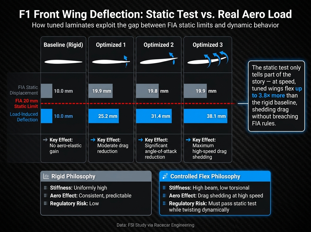
F1 Wing Deflection: Rigid vs. Controlled Flex Laminates Explained
Building on the FSI results, this section looks at a tougher problem: keeping flex inside FIA limits. That space between what a wing does in the lab and what it does on track is where the rule tension sits. It's also where some of the smartest engineering choices happen.
Static Tests, Dynamic Loads, and FIA-Style Deflection Limits

The FIA front wing static test applies a 100 kg (~220 lb) vertical load to the top edge of the endplate and caps deflection at 20 mm (~0.79 in). Engineers can tune beam stiffness and torsional stiffness as separate things. So a wing may pass the static test and still twist once airflow loads it up.
That difference matters. At speed, aerodynamic pressure can make the outer sections twist back. That lowers the angle of attack and sheds drag. A beam deflection check won't show that, because it measures vertical bending, not torsional twist.
As Racecar Engineering noted, the goal is to maximize twist under aero load while still passing the FIA beam-stiffness test.
That's the heart of the controlled-flex approach: split the two stiffness modes instead of treating them as one. Tools such as OptiAssist have been used by F1 championship-winning teams for over 15 years to vary ply orientation and thickness element by element and get that result.
The next issue is more practical: can that flex pattern stay the same after repeated loading, or does it drift?
Fatigue, Micro-Cracking, and Shape Retention Over a Race Distance
Controlled flex only works if the structure can repeat that motion without crossing its strength limit. To handle that risk, engineers build an aerodynamic load failure index into the design process so the wing can twist under load without reaching structural failure.
Repeated aero loading can start micro-cracks and local stiffness loss. So shape retention isn't just about one clean pass on a test rig. It has to hold over a race stint.
Lay-up accuracy has a big role here. It decides whether the wing keeps its planned flex pattern under repeat loading, not just whether it passes inspection. F1 composite parts typically use woven carbon fabric along with unidirectional plies at 0° and ±45°, while virtual draping simulations estimate how complex curves change fiber orientation. Even with those tools, manual ply cleanup is still needed to keep the lay-up manufacturable and continuous.
So the job isn't just to make the wing flex. It's to make it flex the same way lap after lap.
These two design paths mostly differ in how they trade stiffness for aero gain:
| Philosophy | Stiffness Approach | Aero Effect | Regulatory Risk |
|---|---|---|---|
| Rigid | Uniformly high in all directions | Consistent, predictable aerodynamic map | Standard compliance; low risk of scrutiny |
| Controlled Flex | High beam stiffness, low torsional stiffness | Increased ground effect or reduced drag at high speeds | Must pass static tests while twisting dynamically |
The hard part is keeping that controlled twist steady through repeated load cycles.
Surface Quality and the Aero Cost of Imperfections
A wing can hit its target shape and still give away performance. In composite aero, surface quality has a direct effect on drag and downforce because even small defects can upset the airflow.
Surface Finish, Roughness, and Boundary-Layer Behavior
The boundary layer is the thin layer of air closest to the surface. On carbon-fiber aero parts, roughness, pinholes, resin-rich areas, exposed fibers, and waviness can disturb that flow, pushing it toward turbulence earlier and increasing drag. It doesn’t take much. Tiny surface flaws can change how air behaves long before the part looks “bad” to the eye.
A lot of that starts during the build process. The way the part is laid up, cured, and finished plays a big role in how smooth the final surface ends up.
What Roughness Research Means for Carbon-Fiber Wings and Floors
When carbon-fiber plies are draped over complex curves, surface distortion can show up and add drag. So the aero penalty isn’t only about whether the part matches its CAD shape. It also shows up in the finished part’s pressure distribution.
Virtual draping can help by mapping likely defect zones, but final surface quality still depends on precise ply placement. In plain English: software can flag the risk, but the build still has to be right.
That’s why simpler ply patterns are often easier to make the same way, part after part. Limiting ply-region changes cuts down on seams, waviness, and other finish defects. Those shop-floor limits then feed straight into CFD, wind-tunnel work, and track validation.
How Composite Aero Research Reaches the Race Car
From Materials Data to CFD, Wind Tunnel, and Track Validation
Once teams know how a laminate behaves and how the surface holds up, they can turn that research into a part they can actually build and run. The path is tight and practical. It starts with CAD geometry shaped around packaging limits and aero targets, then moves into ply lay-up optimization. After that, engineers use optimization tools to adjust ply thickness and fiber orientation across the structure.
FIA load limits set the starting point, including the 100 kg vertical test and the 20 mm deflection cap. From there, the job is a balancing act. Engineers have to meet those fixed limits while still chasing aerodynamic twist - the controlled flex that helps cut drag on the straights. That’s the point where the work moves past simple structural compliance and into aero validation.
Virtual draping also matters here. It shows where fiber angles can shift around tight curves, which can change how the finished part reacts under load.
Conclusion: Key Findings for F1 Development
The practical takeaway is pretty simple: the best aero parts line up structural behavior, manufacturing, and rule compliance from the very beginning. A wing can pass a static deflection test and still miss the mark if its fiber angles drift from the model or if its aero-elastic behavior changes once it’s built. When that happens, the part won’t produce the performance engineers expected lap after lap.
The strongest studies in this space tie structural modeling to the day-to-day demands of F1 development. They show where the rules leave room for flexible parts, where manufacturing can introduce risk, and how digital tools help close the gap between model predictions and what the part does in physical verification testing.
"The performance of structural composite components under load, aerodynamic or otherwise, remains very much at the top of the designers' priority list." - Racecar Engineering
Composite aero works best when stiffness, flex, surface quality, and manufacturability are tuned together - from material data through CFD, wind tunnel testing, and track correlation.
FAQs
Why can a wing pass FIA tests but still flex on track?
A wing can clear the FIA’s static tests and still bend on track. Why? Because those tests check deflection under set, stationary loads, not the messy aerodynamic forces a car faces at high speed.
So teams build the wing stiff enough to pass inspection. But the carbon-fiber layups can still move under racing loads. On track, that means the wing may twist or deflect in ways the FIA’s static test doesn’t catch.
How do ply angles affect wing twist and drag?
In Formula One, ply angles are the main tool engineers use to control a wing’s torsional flexibility and the way it twists under aerodynamic load.
In most cases, 0-degree plies add bending stiffness, while ±45-degree plies control torsional behavior. By changing that layup, engineers can dial in a controlled twist at high speed. That twist lowers the wing’s angle of attack enough to cut drag, while still keeping cornering downforce and staying within FIA deflection limits.
Why does surface finish matter so much for F1 aero?
Surface finish matters a lot in Formula 1 aerodynamics. Even tiny flaws in the surface can upset airflow, cause flow separation, and cut aerodynamic efficiency and downforce.
At 186 mph (300 km/h), air reacts to even small imperfections or distortions in the bodywork. That’s why teams use CFD and virtual wind tunnel simulations to check pressure across each surface and help keep airflow attached and stable.