Tooling For F1 Carbon Fiber Parts
Compare aluminum, steel, Invar, composite and hybrid tooling for F1 carbon fiber parts: trade-offs in accuracy, heat response, and tool life.
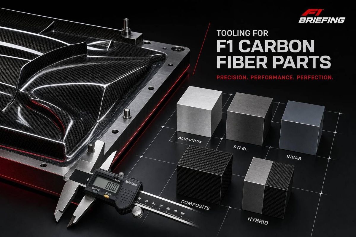
If the tool moves in cure, the part moves with it. That is the core idea here: F1 teams pick tooling based on shape control, heat response, release, tool life, and how fast they need new parts on the car.
I’d boil the article down like this:
- Aluminum is used when I need a tool fast and at lower cost, but its high thermal expansion can shift part shape on large molds.
- Steel lasts a long time and holds shape better than aluminum, but it is heavy and slower to machine.
- Invar is the choice when tight tolerances matter most because its CTE is about 1.2–2.0 × 10⁻⁶/°C, close to carbon laminate behavior.
- Carbon-epoxy molds are light and often a strong fit for short- and mid-run F1 parts, with a better expansion match than aluminum.
- Hybrid tools mix metal support with composite working faces to cut weight while keeping good control.
- Mandrels and inserts handle inner shapes like bores, ducts, and hollow sections.
- Surface coatings and release systems affect demold force, finish, and how long a tool stays usable.
A few numbers make the trade-offs clear. F1 autoclave cures often run at 250–350°F (121–177°C) and up to 100 psi. In that range, aluminum expands at about 23 × 10⁻⁶/°C, while Invar sits near 1.5–2.0 × 10⁻⁶/°C. That gap is a big reason why one tool may suit a front wing update, while another suits a monocoque or floor tool used again and again.
Quick Comparison
| Tooling type | Best use | Main upside | Main drawback |
|---|---|---|---|
| Aluminum | Fast-turn aero tools | Fast machining, high heat transfer | High expansion in cure |
| Steel | Repeat-use production tools | Long life, good wear resistance | Heavy, slower to make |
| Invar | Tight-tolerance parts | Very low expansion | High cost, high weight |
| Carbon-epoxy composite | Short- to mid-run race parts | Low weight, good CTE match | Surface wear over time |
| Hybrid metal-composite | Mid-size aero parts | Balance of weight and control | More process complexity |
| Metal mandrels/inserts | Inner bores, hard points | Tight internal geometry | Removal and mismatch risks |
| Composite/soluble mandrels | Closed ducts, trapped shapes | Can form hard-to-reach cavities | Lower life or single-use |
| Release systems/coatings | All tooling surfaces | Cleaner release, surface protection | Need strict upkeep |
So if you want the short answer, here it is: use aluminum or composite when time matters most, use Invar or steel when repeat accuracy matters most, and use the right mandrel strategy when the geometry is trapped inside the part.
sbb-itb-7c68254
1. Aluminum Molds
Aluminum is a common F1 mold material for a simple reason: it machines fast, polishes well, and works with both oven and autoclave cures. McLaren's Formula 1 team notes that they generally make molds from carbon fiber tooling prepreg or machined and polished aluminum.
That makes aluminum a strong fit for fast-turn parts. The tradeoff is heat-driven growth, which can chip away at accuracy once the tool gets larger.
Dimensional Accuracy
A well-machined aluminum mold can hold tolerances in the range of ±0.02–0.05 mm across typical F1 aero surfaces. That's tight enough for most bodywork, wing elements, and floor panels.
The main issue is thermal expansion. Aluminum's CTE is around 23–24 × 10⁻⁶/°C, so teams have to factor tool growth into CAD and process planning, especially for larger parts. If you picture a long aero tool warming through a cure cycle, the problem becomes pretty clear: even small movement adds up.
One comparative study found that aluminum tooling produced 52.5 mm of deformation under cure conditions, compared with 33.3 mm for steel and just 9.4 mm for composite tooling. To deal with that, teams use CAD scaling and tight cure-cycle control.
Heat Transfer
The same trait that helps speed can also create the main accuracy risk. Aluminum's thermal conductivity is around 167 W/m·K, compared with roughly 0.7 W/m·K for composite tooling.
In practice, that means the mold heats and cools fast, and it tends to do so evenly. That can cut down uneven cure across the laminate and shorten autoclave cycle times. For F1, where part turnaround matters a lot, that kind of heat response is a big plus.
Part Release
Aluminum surfaces need proper prep if you want clean release. Teams usually pair fine machining and polishing with semi-permanent release coatings made for epoxy prepregs.
Hard anodizing adds wear resistance and helps protect the surface from resin chemistry over repeated cycles. Even then, aluminum tools need polishing, release coating, and periodic reconditioning. If that upkeep slips, micro-pitting and high demold force can show up, and that's bad news for thin F1 trailing edges or tight radii during demold.
Tool Life
With aluminum tooling, wear usually sets the limit more than heat does. Aluminum is softer than steel or Invar, so tool life depends a lot on careful handling and cure temperature.
Well-maintained aluminum molds can survive dozens to 100+ cure cycles, which fits parts used for short development runs. In F1, many aero parts become obsolete before the tool wears out, so fast turnaround and lower upfront cost often matter more than long service life.
2. Steel Molds
Steel sits between fast aluminum and low-expansion Invar. It leans more toward dimensional stability than build speed. Its CTE usually lands in the 11–13 µm/m·K range, so it grows less than aluminum during an autoclave cure. In plain terms, that means less shape drift in the tool. Steel still expands much more than Invar or low-CTE composite tooling, but it gives you a tighter hold on geometry than aluminum does.
Dimensional Accuracy
Across a cure cycle, steel molds hold tighter tolerances than aluminum. That said, they’re not the top choice when you need the highest level of precision. Steel still contributes to spring-in and warpage in cured parts, which means CAD compensation is still part of the job. For repeat structural parts, steel is often a good fit. When aero tolerances get tighter, teams usually move to Invar or low-CTE composites.
Thermal Behavior
Steel heats up and cools down more slowly than aluminum, and that can stretch cure cycles. The upside is its thermal mass. It helps smooth out temperature changes across thick sections and complex contours, which can lead to a more even cure. In practice, teams deal with this by mapping thermocouples across the tool during first-article runs and by watching ramp rates and dwell times closely.
Part Release
A well-ground and polished steel surface can reach <0.5 µm Ra, which is smooth enough to reproduce high-quality composite surfaces on a repeat basis. Release coating is mandatory because cured epoxy prepregs stick hard to bare steel. F1 shops usually use thin, semi-permanent, silicone-free release coatings applied in several layers. Steel also tends to resist surface damage from repeated demolding better than aluminum, so gloss and surface finish last longer. That only holds if corrosion stays under control and the release agent matches the resin system.
Release coating is mandatory, as cured epoxy prepregs bond aggressively to bare steel.
Tool Life
This is where steel makes its case. Metal molds can survive thousands of autoclave cycles, which makes steel a strong pick for parts built again and again during a season or across multiple years. For suppliers making structural components at moderate-to-high volumes, that long service life can push cost per part down over time.
When dimensional control needs to go even further, Invar is usually the next step.
3. Invar Molds
When steel still can't hit the tolerance target, teams step up to Invar 36. It's a nickel-iron alloy with a CTE of about 1.2–2.0 × 10⁻⁶/°C - roughly 10 times lower than aluminum or steel tooling. That solves a lot of precision issues, but it comes with tradeoffs: more weight, more machining time, and a much higher price. So Invar is the pick for precision, not for speed.
Dimensional Accuracy
Carbon fiber/epoxy laminates expand at about 0–2 × 10⁻⁶/°C in the fiber direction, which puts Invar much closer to the part than most metal tooling choices. That match matters. When the mold and the part expand and contract at nearly the same rate during autoclave cure, you get much less spring-in, warpage, and long-term shape drift.
That kind of stability shows up over time too. Aerospace tooling data shows Invar tools can hold contour accuracy through 500+ autoclave cure cycles, while aluminum tools under similar conditions can build up 2–5 mm of distortion. For F1 parts like front wing mainplanes, major floor elements, or monocoque shells, that's hard to brush aside.
Thermal Behavior
Invar's low expansion only holds while it stays in the right magnetic state. Above about 240–280°C (464–536°F), that edge starts to fade. For standard F1 autoclave cures in the 120–180°C (248–356°F) range, Invar stays comfortably inside its low-expansion window. If cure temperatures climb past 200–240°C (392–464°F), engineers need to check that the alloy is still operating in range.
There's another tradeoff here: Invar heats up and cools down more slowly than aluminum. On large tools, that can mean longer ramp and soak times, or the use of hybrid backing structures, to keep temperature even across the mold. The upside is that this thermal stability can also help the tool surface and release system last longer.
Part Release
Invar molds are usually polished, nickel-plated, and paired with semi-permanent release agents that match the resin system. Since Invar expands so little during thermal cycling, the mold surface puts less strain on the release film than aluminum does. That can help the coating last longer and lower the chance of local sticking, especially on sharp aero features.
Nickel plating over the Invar base also improves corrosion resistance and helps the surface finish hold up over time.
Tool Life
Invar is dense - about 8.1 g/cm³ (0.29 lb/in³), which is close to steel - so large Invar molds are heavy and tougher to move and support. Then there's cost. Invar can run $5,000–$10,000 per cubic foot, versus $300–$1,000 per cubic foot for aluminum.
That's why F1 teams save full Invar tools for the parts where tolerance matters most and where the mold has to stay stable across many cycles. If a full Invar mold gets too large or too expensive, teams often use hybrid setups instead. And when lower weight and faster build times matter more, they switch to carbon-epoxy composite molds.
4. Carbon-Epoxy Composite Molds
Carbon-epoxy molds are a strong fit for short- to medium-run F1 parts because they’re light, fast to make, and less expensive than Invar. Teams often build them from tooling prepreg over a machined master, then add a fine surface ply to improve finish. In practice, composite tooling sits in the middle ground between fast aluminum tools and more stable Invar tools.
Dimensional Accuracy
The big technical plus with carbon-epoxy molds is the thermal expansion match between the tool and the part. Carbon/epoxy parts expand at about 2.9–3.66 µm/m/°C, and well-made composite tooling can be built to follow that behavior closely. Low-CTE tooling resins shrink the gap even more and help the mold move with the part during cure.
That matters because the mold has to match more than the part’s shape. It also has to match how the part moves through the cure cycle. When both tool and part expand and contract at similar rates, spring-back and warpage go down. The result is a part that lands closer to its target cured shape, which is a big deal on tight aero surfaces such as front wing profiles and floor edges.
Balanced quasi-isotropic layups and stiff backing ribs help keep large tools stable without adding much weight.
Thermal Behavior
Carbon-epoxy tools heat up and cool down faster than Invar because they weigh much less, but their low conductivity can make temperature control tougher. In F1, where mold turnaround between events matters, that faster thermal cycling is a clear plus.
To deal with the control side, engineers usually:
- limit ramp rates
- add intermediate dwells
- time pressure application so the tool and part equalize before resin crosslinking moves too far
Most epoxy-based composite tooling systems are rated for continuous service at 250–355°F (120–180°C), which fits standard F1 autoclave cure windows well. Before a tool goes into production, teams post-cure it to push its glass transition temperature above the planned part cure temperature and lock in the mold geometry. That same thermal discipline also helps protect the gelcoat and maintain release performance.
Part Release
Composite molds usually rely on a polished epoxy gelcoat and semi-permanent release agents. Regular cleaning, reapplication, and occasional repolishing help keep release steady.
Over time, the main risk is microscopic surface print-through or microcracking if the tool is used again and again near its Tg limit. That can trap resin and make release less predictable.
Tool Life
When used the right way, carbon-epoxy tooling can last for hundreds of autoclave cycles with little dimensional drift. For many F1 jobs, that puts it in the same general range as Invar.
In day-to-day use, tools are more likely to be retired because of wear, edge chipping, or drift than because the structure itself fails. So the trade-off is pretty simple: composite tools make sense for short- and medium-run race parts, while Invar and steel are still the better pick for the highest-cycle, most dimension-sensitive geometries. When composite skins need more stiffness or metal wear surfaces, teams shift to hybrid metal-composite tools.
5. Hybrid Metal-Composite Molds
When a full composite tool needs more stiffness or better wear resistance, teams usually switch to a hybrid build. Hybrid metal-composite molds use a metal backing structure with a composite face sheet that touches the laminate directly. The metal - often Invar, steel, or aluminum - handles stiffness and support. The composite face cuts weight and helps the tool follow more complex shapes.
That mix makes a lot of sense for mid-size aero parts like wing elements and brake ducts, where a full Invar tool can be too heavy or too expensive.
Dimensional Accuracy
Accuracy in a hybrid mold comes down to one thing: CTE matching between the backing structure and the face sheet. When an Invar base is paired with a well-designed carbon-epoxy face sheet, the tool can hold tolerances within ±0.1–0.2 mm over repeated cycles.
The metal backing helps keep the face sheet in check during cure, which reduces drift. But there’s no room for guesswork here. If the CTE mismatch isn’t engineered with care, a hybrid tool can distort more than a full-metal or full-composite mold. In plain terms, the material pairing can make or break the result.
Thermal Behavior
Hybrid molds sit between full-metal and full-composite tools when it comes to thermal mass. The metal backing spreads heat more evenly than a bare composite tool. At the same time, the lighter face sheet helps speed ramp rates without hurting surface uniformity.
That’s a big plus during a packed race calendar, when autoclave throughput matters and time disappears fast. For parts cured at higher temperatures - around 350°F (177°C) - teams usually specify high-temperature face-sheet resins so the interface can handle repeated cycles.
Part Release
Release performance in hybrid molds depends mostly on the composite face sheet’s surface treatment, since that’s the part touching the laminate. Teams use semi-permanent, silicone-free release agents matched to the resin system. In some cases, they also add PTFE-based coatings on tight radii and high-load zones.
The metal backing gives the tool more mechanical support during demolding without hurting the composite surface. A common trouble spot is edge damage on the composite face, which is why strict handling rules are standard.
Tool Life
Hybrid Invar/composite molds can cut weight and lead time while still holding vacuum integrity and precision. In day-to-day use, the metal base usually lasts longer than the composite face, which may need resurfacing or local repair after many high-temperature cycles.
That’s a strong fit for F1. Teams can rebuild or replace the composite face to update aero geometry while keeping the same metal substructure. In a sport built around fast iteration, that’s a direct edge. The split between structure and working surface also sets up the move into mandrels and inserts.
6. Metal Mandrels and Inserts
Metal mandrels and inserts control internal geometry, not the outer skin. In plain terms, they shape what happens inside the part: hollow cores, bearing seats, and load-bearing hard points. That includes the hollow sections in suspension wishbones, steering columns, and structural tubes inside the monocoque. If the mold sets the outside surface, the mandrel or insert sets the cavities and the load paths within it.
Dimensional Accuracy
The hardest part with metal mandrels is thermal expansion mismatch. Aluminum expands at about 23 × 10⁻⁶/°C during an autoclave cycle, while a carbon laminate expands at only a small fraction of that. That difference can ovalize bores and distort tight radii.
Invar cuts that problem down in a big way. Its CTE is about 1.2 × 10⁻⁶/°C, which is much closer to the carbon laminate. That lets teams hold inner bores and tube diameters to ±0.02–0.05 mm over repeated cycles. For suspension pickups and bearing housings, that's the goal.
To keep those numbers in check, teams rely on 5-axis CNC machining, in-process probing, and CMM verification. The idea is simple: make sure mandrel geometry stays within spec across its service life. Once the geometry is right, cure-temperature growth becomes the next limit to manage.
Thermal Behavior
Aluminum mandrels heat up fast and move that heat into the laminate well, which helps cure uniformity in shorter parts. But there's a catch: aluminum also expands a lot. So teams often machine aluminum mandrels slightly undersized at room temperature, letting the tool grow into the right geometry at cure temperature.
Invar doesn't need that kind of compensation. Its dimensions shift very little during cure, which makes process setup easier and lowers the chance of laminate distortion. Tool steels sit somewhere in the middle, with higher wear resistance and a moderate, more predictable level of expansion.
Part Release
Removal depends on what the tool is meant to do. Split or segmented mandrels use parting lines placed along neutral stress zones, then get unbolted and removed piece by piece after cure. It's a bit like taking apart a ship in a bottle, except the planning starts long before cure day.
Polished metal surfaces below Ra 0.4 µm, paired with semi-permanent fluoropolymer or PTFE-based release coatings, stop cured epoxy from sticking to the tool. Split mandrels are removed after cure. Permanent inserts, such as bearing seats and hard points, stay in place. In those cases, teams grit-blast or etch the bond zone so the insert bonds where it should, while nearby surfaces stay masked and release-coated.
Tool Life
For inserts, removal matters less than retention and load transfer. Bonded-in metal inserts - bearing seats, threaded bosses, and mounting flanges - have to handle torque, vibration, and clamp load without working loose.
That means insert geometry is built with flanges or undercuts to create a mechanical interlock with the carbon plies. Teams also use finite element analysis to spread peak stresses across a larger area. Mandrels come out after cure; inserts stay behind as part of the structure.
Tool condition is checked on a schedule, not by guesswork. Teams send tools for CMM inspection at set intervals and retire or refurbish them before measurable drift affects part quality. Aluminum mandrels are repolished, re-anodized, or recoated. Invar and steel tools are reground or re-lapped.
7. Composite and Soluble Mandrels
Composite and soluble mandrels handle a job that rigid metal cores simply can’t: they can be removed from closed cavities and tight duct shapes after cure. That makes them a strong fit for intake trunks, airbox ducts, sidepod internal ducting, brake ducts, and routing tubes. Compared with the reusable metal cores in the previous section, the trade is simple: less life, easier removal.
Dimensional Accuracy
Composite mandrels are usually made from carbon/epoxy, glass/epoxy, or BMI. They’re machined from masters or printed patterns, then laid up to keep their shape under vacuum and autoclave pressure. Teams also account for spring-in through tested cure cycles. Toray reported ±0.25 mm across the surface and under 0.1 mm of deflection under a 220 lb (100 kg) center load.
Soluble mandrels use water-soluble salts, low-melting alloys, or dissolvable polymers. These can be cast or machined into precise forms, but there’s a catch: they tend to be brittle. That makes them easier to chip or crack during layup and bagging, which can hurt dimensional control, especially in long, narrow ducts.
Thermal Behavior
Composite mandrels can be set up to better match the laminate’s coefficient of thermal expansion, and they heat more slowly, which helps limit thermal gradients. Soluble salts and polymers usually have a higher CTE and lower thermal stability, so they call for gentler ramp rates and medium-temperature epoxy systems.
To keep this under control, engineers check mandrel materials with DMA and DSC testing and stay away from sharp corners, where thermal stress tends to pile up.
Part Release
Composite mandrels come out through mechanical extraction. In practice, that usually means polished resin-rich surfaces, semi-permanent PTFE-based coatings, and segmented or collapsible core designs so the mandrel can be slid or lightly tapped free after cure.
Soluble mandrels take a different route. They’re washed out, melted, or chemically dissolved after cure. Stratasys notes that heated detergent circulation can cut dissolving time by 75% or more, which is a big deal when turnaround matters. Teams then confirm full removal with borescope inspection or a mass check before final sign-off.
Once the core is out, surface coating and release chemistry still shape demold force and finish quality. In other words, getting the mandrel out is only part of the story.
Tool Life
Composite mandrels are multi-cycle. Soluble mandrels are single-use.
Here’s how the split looks in practice:
| Criterion | Composite Mandrel | Soluble Mandrel |
|---|---|---|
| Dimensional accuracy | High; CTE-matched and stiff under pressure | Moderate; brittleness limits control in slender ducts |
| Thermal behavior | Good CTE match to laminate; slower heat transfer | Higher CTE; needs conservative cure ramps |
| Part release | Mechanical extraction; draft angles and coatings required | Dissolved or washed out; no extraction force on part |
| Tool life | Multi-cycle; inspected and refurbished on schedule | Single-use; new core required for each part |
| Best fit | Stable, repeated duct geometries; moderate-to-high volume | Complex undercuts, closed cavities, rapid design iteration |
After the core is removed, surface coating and release chemistry decide how cleanly the part demolds.
8. Tool Surface Coatings and Release Systems
Once the core or mold is ready, the surface system often decides how the next step goes: clean release or tool damage. And there’s a catch. The same release system won’t act the same way on polished steel, nickel-plated Invar, and composite gelcoats.
Dimensional Accuracy
The main problem is uneven buildup. If the release film goes on too thick - or just goes on unevenly - it adds measurable thickness to the mold face. In tight aero work, that can move dimensions enough to matter.
That’s why F1-style tooling usually uses thin, uniform, semi-permanent systems. They keep film build low and help reduce print-through. For a new mold, prep usually follows four steps: cleaner, sealer, primer, release.
Thermal Behavior
Release chemistry has to make it through the full cure cycle without breaking down. In 180°C (356°F) autoclave epoxy processes, suppliers call for a decomposition onset above 220°C (428°F) to keep a safe margin.
Wax releases top out near 115°C (240°F) and aren’t a fit for autoclave prepreg. High-temperature semi-permanent systems are used for epoxy, BMI, and PEEK cures. To protect bond lines and paint adhesion, fluoropolymer and other non-silicone chemistries are preferred. These systems are put on in multiple coats at or above 100°C (212°F), and they can support multiple demolds before reapplication.
Part Release
The day-to-day choice comes down to three things:
- Cure temperature
- Resin chemistry
- How many demolds the surface needs to survive
A release system that works fine for a low-temp epoxy part may fail fast in a high-heat PEEK cycle. That’s where surface choice stops being a shop preference and starts being process control.
Tool Life
In F1, coating drift often ends tool life before the tool itself fails structurally. If a coating wears unevenly or gets contaminated by the wrong cleaner, release behavior can change from one cycle to the next. Then part quality starts to wander.
Abrasive cleaning, incompatible solvents, and over-polishing all cut coating life short. The way shops avoid that is pretty simple: keep a strict cleaning and reapplication schedule, and check that cleaners and release chemistry work together. That’s what keeps the tool repeatable over many cycles.
The table below compares the main release systems by temperature window and best fit.
| Release System | Max Temperature | Best Fit | Key Limitation |
|---|---|---|---|
| Wax-based | ~115°C (240°F) | Low-temp, simple parts | Not suitable for autoclave prepreg |
| Semi-permanent (solvent-based) | 175–260°C (347–500°F) | Epoxy, phenolic, BMI prepreg | Requires controlled application |
| Semi-permanent (water-based) | Up to 400°C (752°F) | Autoclave, press molding, PEEK | Needs careful process control |
| High-temp aerospace-grade | 350–450°C (662–842°F) | BMI, PEEK, high-temp thermoplastics | Specialized high-temperature use |
Trade-Offs By Performance Criterion
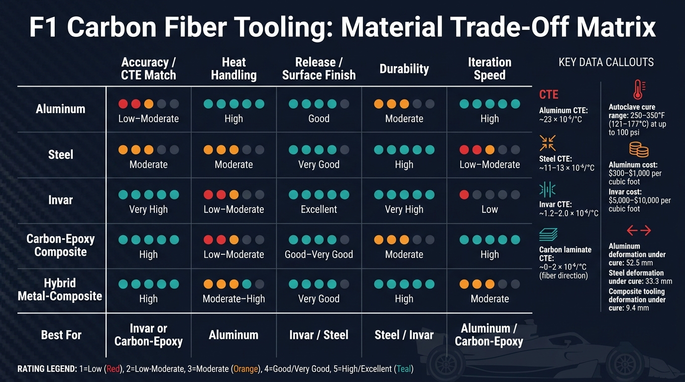
F1 Carbon Fiber Tooling Materials: CTE, Cost & Performance Compared
Once the mold surface and release system are locked in, the next step is simpler to say than to solve: which tooling material gives you the right mix of accuracy, heat behavior, and service life?
Accuracy and stability during cure come down to CTE match. Invar is the closest match to the part. Aluminum is the farthest off. Steel and low-CTE composite tooling land in the middle. That’s why Invar and carbon-based tooling are often the go-to pick when even small cure-cycle movement can turn into a measurable aero penalty.
Heat handling is where aluminum has a clear edge. Its high thermal conductivity helps the tool get up to temperature faster and with better uniformity. Aluminum heats and cools the fastest and most evenly. Steel and Invar react more slowly and need tighter ramp control. Composite tooling also takes longer to equalize through its thickness.
Release and surface finish matter just as much as dimensional control. Polished steel and Invar tools can produce excellent finishes and are often used with semi-permanent release agents. Composite tools can also deliver very good surfaces, but they rely more on careful release chemistry and periodic refurbishment. Hybrid tools aim to blend the smooth, durable working face of metal with the lower weight and CTE upside of composite structures.
Durability versus build speed is the toughest trade-off in the set. Steel and Invar tools can handle repeated cycles and keep their shape over time, but large tools take longer to machine and build. Cost tends to follow the same curve: aluminum is the cheapest, Invar is the most expensive, and composite tooling sits in between. Carbon-epoxy composite tooling is faster to make from a master pattern, while aluminum is easier to machine but usually gives up some long-run stability.
The matrix below condenses the comparison into the five criteria that matter most.
| Tooling Category | Accuracy / CTE Match | Heat Handling | Release / Surface Finish | Durability | Iteration Speed |
|---|---|---|---|---|---|
| Aluminum | Low–Moderate | High | Good | Moderate | High |
| Steel | Moderate | Moderate | Very Good | High | Low–Moderate |
| Invar | Very High | Low–Moderate | Excellent | Very High | Low |
| Carbon-Epoxy Composite | High | Low–Moderate | Good–Very Good | Moderate | High |
| Hybrid Metal-Composite | High | Moderate–High | Very Good | High | Moderate |
Hybrid tooling closes part of the gap by mixing metal stability with composite weight savings and faster build response. For teams working under compressed development timelines, that trade can end up being the deciding factor. The next section turns this ranking into a clear pros-and-cons summary.
Pros and Cons
The matrix above turns the trade-offs into a quick selection guide. This table narrows the main F1 tooling options by accuracy, heat behavior, durability, and turnaround time.
| Tooling Type | Key Pros | Key Cons |
|---|---|---|
| Aluminum | Lightweight, fast to machine, high thermal conductivity, low cost | High CTE (~23×10⁻⁶/°C) can lead to dimensional drift; moderate durability; surface damage risk with repeated handling |
| Steel | High durability, good wear resistance, moderate CTE (~11–13×10⁻⁶/°C) | Heavy, slow to machine, corrosion risk in autoclave settings, less suited to frequent geometry changes |
| Invar | Extremely low CTE (~1–2×10⁻⁶/°C), very stable dimensions | Very heavy, slow and costly to machine, long lead times, hard to modify once built |
| Carbon-Epoxy Composite | Lightest option, fast to produce from a master pattern, lower CTE than aluminum, good for short runs and test parts | Shorter service life, surface microcracking over time, less predictable long-term expansion, needs more frequent refurbishment |
| Hybrid Metal-Composite | Balances weight and precision, metal in critical zones helps hold local stability, can be resurfaced or repaired in spots | Maintenance calls for both metal and composite repair skills; mixing dissimilar materials adds process complexity |
| Metal Mandrels/Inserts | Very repeatable for internal geometry (bores, bearing seats), high durability, precise under cure loads | Add localized weight, hard-to-reach geometry increases demolding risk, wear and galling with repeated use |
| Composite/Soluble Mandrels | Allow complex internal geometries for repeat release performance, lighter than metal versions, removed without mechanical force | Often single-use, expansion during cure can be hard to predict, dissolution or melt-out adds process steps and contamination risk |
| Surface Coatings/Release Systems | Semi-permanent systems provide multiple releases per application, protect tool surface, reduce resin adhesion | Must be reapplied on a set schedule, poor application can cause sticking or surface defects, plated surfaces need inspection for wear or peeling |
That’s the practical split: fast-turn tools for aero parts that keep changing, and stable tools for geometry that’s locked down. Aluminum or carbon-epoxy make sense when updates come fast. Steel or Invar fit better when the shape is fixed and cycle count is high.
Conclusion
F1 tooling choice comes down to four things: geometry tolerance, cure-cycle count, turnaround time, and internal part complexity. Once those are clear, the choice usually comes down to tool material.
Invar is the top pick when precision and long service life matter most. Steel makes sense for repeat use and strong wear resistance. Aluminum is a good fit for fast, lower-cost development tooling. Carbon-epoxy composite molds work well when the team needs to move fast, the part is large, or lower tool weight matters. Hybrid tooling makes sense when you need the stability of metal with the lower weight of composite.
For internal geometry, the decision shifts. At that point, it’s less about mold material and more about core strategy. When geometry is trapped inside the part, composite or soluble mandrels are the right call.
Surface coatings and release systems also play a big part. They affect demold force, finish quality, and tool life.
The table below turns those trade-offs into a quick use-case guide.
| F1 Use Case | Recommended Tooling |
|---|---|
| Structural parts (highly loaded suspension components) | Invar or metal-heavy hybrid molds; inserts for local wear or load-bearing zones |
| Aero surfaces (wings, bodywork, diffusers) | Carbon-epoxy composite or hybrid molds; semi-permanent release systems |
| Internal ducting (closed passages and hollow sections) | Composite or soluble mandrels; sacrificial cores for trapped geometry |
FAQs
Why is Invar preferred for tight-tolerance F1 parts?
In Formula One, teams often choose Invar for high-precision molds because it expands and contracts very little when heat kicks in. That matters during the high-temperature curing process, where standard metals can shift enough to throw off the final shape.
Invar stays dimensionally stable through those heat cycles. As a result, carbon fiber parts can keep the tight tolerances needed for aerodynamic consistency and FIA compliance.
When would a team choose composite tooling over aluminum?
Teams usually pick composite tooling over aluminum for one main reason: thermal expansion compatibility during the high-temperature curing of carbon fiber parts.
Here’s the simple version. When the mold and the part are made from the same material, they expand and contract at a similar rate as heat goes up and down. That helps avoid differential expansion, which can lead to internal stress, surface distortion, or dimensional inaccuracy.
For high-precision structural components, that match matters a lot. Even small movement during curing can throw off the final part.
How do mandrels and release coatings affect part quality?
In Formula One carbon fiber manufacturing, mandrels shape the inside of a part during layup and curing. That matters a lot when teams are building complex components that need tight, repeatable dimensions.
Release coatings help finished parts come out of molds cleanly, without damage or warping. In plain terms, they stop the part from sticking too much, which helps protect the smooth surface finish that aerodynamic performance and strict quality standards depend on.